
| Tweet |

Custom Search
|
|

|
||
 3500 ENGINE
SPECIFICATIONS
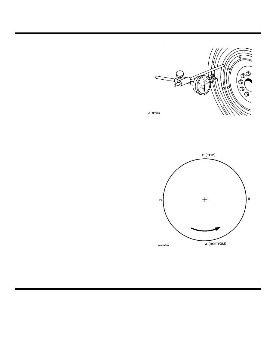
FLYWHEEL HOUSING RUNOUT
Face Runout (axial eccentricity) of the Flywheel
Housing:
8S2328 DIAL INDICATOR GROUP INSTALLED
1.
Fasten a dial indicator to the crankshaft flange
(TYPICAL EXAMPLE)
so the anvil of the
Indicator will touch the face
of the flywheel housing.
2.
Put a force on the crankshaft toward the rear
before reading the indicator at each point
3
With dial indicator set at 0 0 mm (.000 in.) at
location (A), turn
the crankshaft and read the
indicator at locations (B), (C) and (D)
4.
The difference between lower and higher
measurements taken at all four points must not
be more than 0.30 mm (.012 in.), which is the
maximum permissible face runout (axial
eccentricity) of the flywheel housing.
NOTE: FOR TORQUE VALUES NOT GIVEN, SEE THE FIRST
PAGE OF SPECIFICATIONS FOR GENERAL TIGHTENING TORQUES
53
|
||
|
||


