
| Tweet |

Custom Search
|
|

|
||
 FUEL SYSTEM
SYSTEMS OPERATION
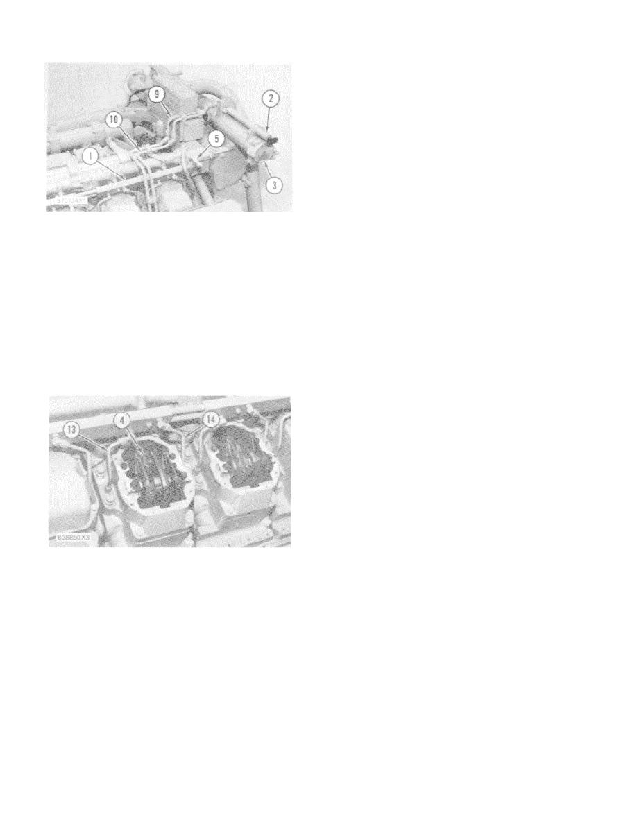
FUEL FLOW THRU INJECTOR
4. Injector. 13. Outlet fuel line. 14. Inlet fuel line.
15. Drilled passage. 16. Cylinder head. 17. Cylinder.
Check each engine installation for an excess fuel
flow based on fuel consumed (used for combustion).
Minimum flow is three times the amount of fuel
consumed. Excess fuel is then returned to the fuel tank,
not back to the pump inlet. This will make sure that any
air in the system will be removed before the fuel is sent
back to the injectors.
RIGHT SIDE OF ENGINE
1. Fuel manifold (right hand). 2. Priming pump. 3.
Pressure regulating valve (2) has a spring and
Fuel filter housing. 5. Pressure regulating valve. 9.
plunger arrangement between the bottom section of the
Fuel line to filter housing (from transfer pump). 10.
fuel manifolds and the line that returns fuel to the tank.
Fuel line to priming pump (from transfer pump).
This valve keeps the pressure of the fuel at 415 to 450
kPa (60 to 65 psi) in the cylinder heads and fuel
ed to the right side of each cylinder head. On earlier
manifolds. The valve also has resistance to fuel flow but
engines, filter screens are located in the fittings where
little resistance to air. This helps re- move (bleed) air
fuel goes into each cylinder head. On later engines, the
from the fuel injection system when the engine is in
filter screens are located in the ports of the unit injector.
operation. The air is returned to the fuel tank and vented
A drilled passage (15) in cylinder head (16) takes fuel to
to the atmosphere.
a circular (shape of a circle) chamber around the
injector. The chamber is made by O-rings on the outside
A small orifice connects the inlet and outlet
diameter of injector (4) and the injector bore in the
passages in the adapter (housing) of pressure regulating
cylinder head.
valve (2). The orifice is used as a syphon break when
the fuel filters are changed. This keeps the fuel lines and
manifolds from being drained and the use of fuel priming
pump (4) is not normally needed. The fuel priming pump
must be used when the lines are dry. For example: after
an overhaul or other major fuel system work.
CYLINDER HEADS
3. Fuel injector. 13. Outlet fuel line. 14. Inlet fuel
line.
Only part of the fuel in the chamber is used for injection.
Approximately 4/2 times as much fuel as needed for
normal combustion flows through the chamber to a
drilled passage in the left side of the cylinder head. This
passage is connected by outlet fuel line (13) to the
bottom section of the fuel manifold. This constant flow of
fuel around the injectors helps to cool them.
The fuel flows back through the bottom section
of each fuel manifold to pressure regulating valve (2), on
the front of the right fuel manifold. The fuel flows
through this valve and then back to the tank.
66
|
||
|
||


