
| Tweet |

Custom Search
|
|

|
||
 ELECTRICAL SYSTEM
SYSTEMS OPERATION
linkage to engage with the ring gear on the flywheel of
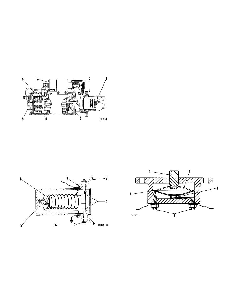
There are contacts (4) on the end of core (6).
the engine. The starter pinion will engage with the ring
The contacts are held in the open position by spring (5)
gear before the electric contacts in the solenoid close the
that pushes core (6) from the magnetic center of coil (1).
circuit between the battery and the starter motor. When
Low current will energize coil (I) and make a magnetic
the circuit between the battery and the starter motor is
field. The magnetic field pulls core (6) to the center of
complete, the pinion will turn the engine flywheel. A
coil (I) and the contacts close.
clutch gives protection for the starter motor so that the
engine, when it starts to run, can not turn the starter
motor too fast. When the start switch is releasd, the
starter pinion will move away from the flywheel ring gear.
OTHER COMPONENTS
Circuit Breaker
The circuit breaker is a switch that opens the
battery circuit if the current in the electrical system goes
higher than the rating of the circuit breaker.
A heat activated metal disc with a contact point
completes the electric circuit through the circuit breaker.
If the current in the electrical system gets too high, it
causes the metal disc to get hot. This heat causes a
distortion of metal disc which opens the contacts and
breaks the circuit. A circuit breaker that is open can be
reset after it cools. Push the reset button to close the
STARTER MOTOR
contacts and reset the circuit breaker.
1. Field. 2. Solenoid. 3. Clutch. 4. Pinion. 5.
Commutator. 6. Brush assembly. 7. Armature.
NOTICE
Starter Solenoid
Find and correct the problem that causes the circuit
breaker to open. This will help prevent damage to
A solenoid is a magnetic switch that causes low
the circuit components from too much current.
current to close a high current circuit. The solenoid has
an electromagnet with a core (6) which moves.
CIRCUIT BREAKER SCHEMATIC
1. Reset button. 2. Disc in open position. 3. Contacts.
4. Disc. 5. Battery circuit terminals.
SCHEMATIC OF A SOLENOID
1. Coil. 2. Switch terminal. 3. Battery terminal. 4.
Contacts. 5. Spring. 6. Core. 7. Component terminal.
89
|
||
|
||


