
| Tweet |

Custom Search
|
|

|
||
 FUEL SYSTEM
TESTING AND ADJUSTING
2.
Move the governor or actuator terminal shaft in
NOTE:
See FUEL SETTING AND
RELATED
the fuel "ON" direction until the flat face of fuel
INFORMATION for the correct fuel setting.
stop lever (6) contacts synchronizing pin (5).
Hold the linkage in this position.
5.
If fuel setting is correct, remove the dial indicator
and synchronizing pin (5). Install the two plugs,
and install pin (5) back into cover (8).
6.
If fuel setting needs adjustment, go on to Fuel
Setting Adjustment.
Fuel Setting Adjustment
NOTICE
A mechanic with governor and fuel setting training is
the ONLY one to make adjustments to the engine
fuel setting.
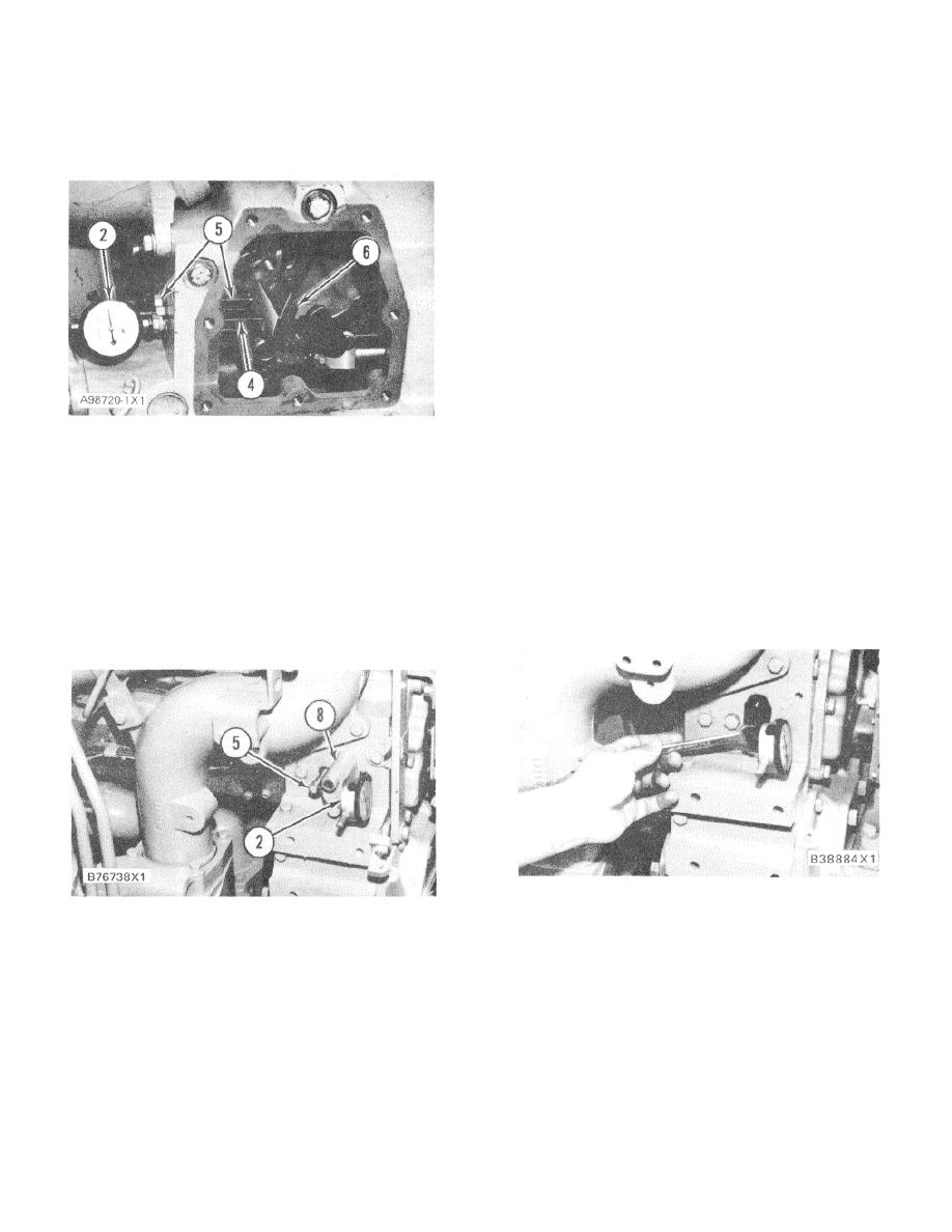
DIAL INDICATOR IN POSITION
(Cover Removed Only for Photo Illustration)
1.
Cut the seal wire and remove fuel setting cover
2. 6V3075 Dial Indicator. 4. 5P7263 Contact Point,
(8) and the gasket. Loosen locknut (7) and (with
76.2 mm (3.00 in.) long. 5. Synchronizing pin. 6.
fuel stop lever still held against end of the fuel
Fuel stop lever.
setting screw) turn the fuel setting screw in or
out until the correct reading is on the dial
3.
Install the dial indicator and collet (3) in the
indicator.
threaded hole as shown. When the contact point
seats against fuel stop lever (6), slide the dial
indicator in or out until the indicator reads zero.
Now tighten collet (3) just enough to hold
indicator at this position.
ADJUSTMENT OF THE FUEL SETTING SCREW
CHECKING FUEL SETTING
2. 6V3075 Dial Indicator (metric). 5. Synchronizing
pin. 8. Fuel setting cover.
2.
Now tighten locknut (7). Be sure that the fuel
setting screw does not turn when the locknut (7)
4.
Turn synchronizing pin (5) back out a minimum
is tightened. Release the fuel linkage and again
of 25 mm (1 in.) (or remove it completely), and
move linkage all the way in the fuel "ON"
then slowly move the governor or actuator
direction. Check the dial indicator reading again
terminal shaft in the fuel "ON" direction until the
to be sure that fuel setting is still correct.
flat face of the fuel stop lever is against the end
of the fuel setting screw. With the linkage held
3.
Remove the dial indicator and synchronizing pin
in this position, the dial indicator reading will be
(5), then install the two plugs. (5), then install the
the present fuel setting.
two plugs.
126
|
||
|
||


