
| Tweet |

Custom Search
|
|

|
||
 3161 GOVERNOR
TESTING AND ADJUSTING
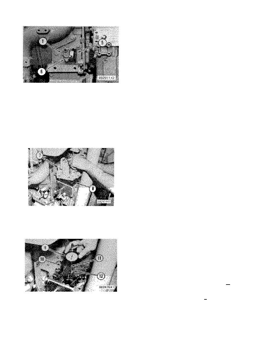
housing with bracket assembly (10) as follows:
Use a top cover bolt with three washers (as
spacers under the bolt head) on it and put the
bolt through the fixed diameter hole in the
bracket. Fasten the bracket to the left side of
the housing in the second threaded hole from
the front. Put the dial indicator in the adjustable
hole in the bracket assembly and position it so
the indicator contact point (11) rests on the bolt
head (12) of the torque control lever.
INSTALL DIAL INDICATOR
8.
Check to make sure the cam follower is on the
base circle of the governor torque rise cam. See
1. Synchronizing pin. 5. 6V3075 Dial Indicator. 6.
Systems Operation section for a description of
Fuel setting cover.
the base circle.
5.
Put dial indicator (5) with the 5P7263 Contact
9.
Move dial indicator (9) until it reads zero and
Point in the 5P4814 Collet. Install dial indicator
fasten it in place.
(5) and the collet in the threaded hole for plug
(3). When the contact point seats against the
10.
Turn the synchronizing pin out of the engine front
fuel stop lever, slide the dial indicator in or out
drive housing a minimum of half-way. As the
until it reads zero. Now tighten the collet just
synchronizing pin is backed out, dial indicator (5)
enough to hold dial indicator (5) at this position.
will follow the fuel control linkage movement until
the fuel control linkage stop lever contacts the
fuel setting screw. Dial indicator (5) now shows
the torque rise fuel setting. Make sure the
torque rise fuel setting is correct. If not, an
adjustment is necessary.
11.
Look in the Fuel Setting and Related Information
Fiche for the full load setting for the engine you
are adjusting.
12.
Turn the synchronizing pin in until dial indicator
(5) reads the full load fuel setting. The full load
setting is a reference position and is a temporary
REMOVE GOVERNOR TOP COVER
setting used to adjust the torque rise cam
7. Cover. 8. Gasket.
position.
6.
Remove the bolts that hold cover (7) in position.
The purpose of this procedure is to hold the fuel
Lift cover (7) off the governor and remove gasket
control linkage at the full load setting while the
(8).
torque rise cam is adjusted.
13.
Dial indicator (9) must read 1.00 + 0.05 mm, if it
does not, an adjustment is needed. Loosen the
bolt that holds the cam enough so the cam can
be moved, but keep the bolt tight enough to
provide a small drag on the cam.
14.
Slide the cam to cause the torque control lever
and dial indicator contact to lift 1.00 + 0.05 mm.
15.
Tighten the bolt while the cam is held in place.
INSTALL DIAL INDICATOR
This adjustment of 1.00 + 0.05 mm positions the
9. 6V3075 Dial Indicator. 10. 9S228 Bracket
torque control lever so the torque rise (additional
Assembly. 11. 3S3269 Contact Point. 12. Bo8t.
fuel) begins to occur at the correct engine speed.
7.
Install dial indicator (9) on the top of the governor
190
|
||
|
||


