
| Tweet |

Custom Search
|
|

|
||
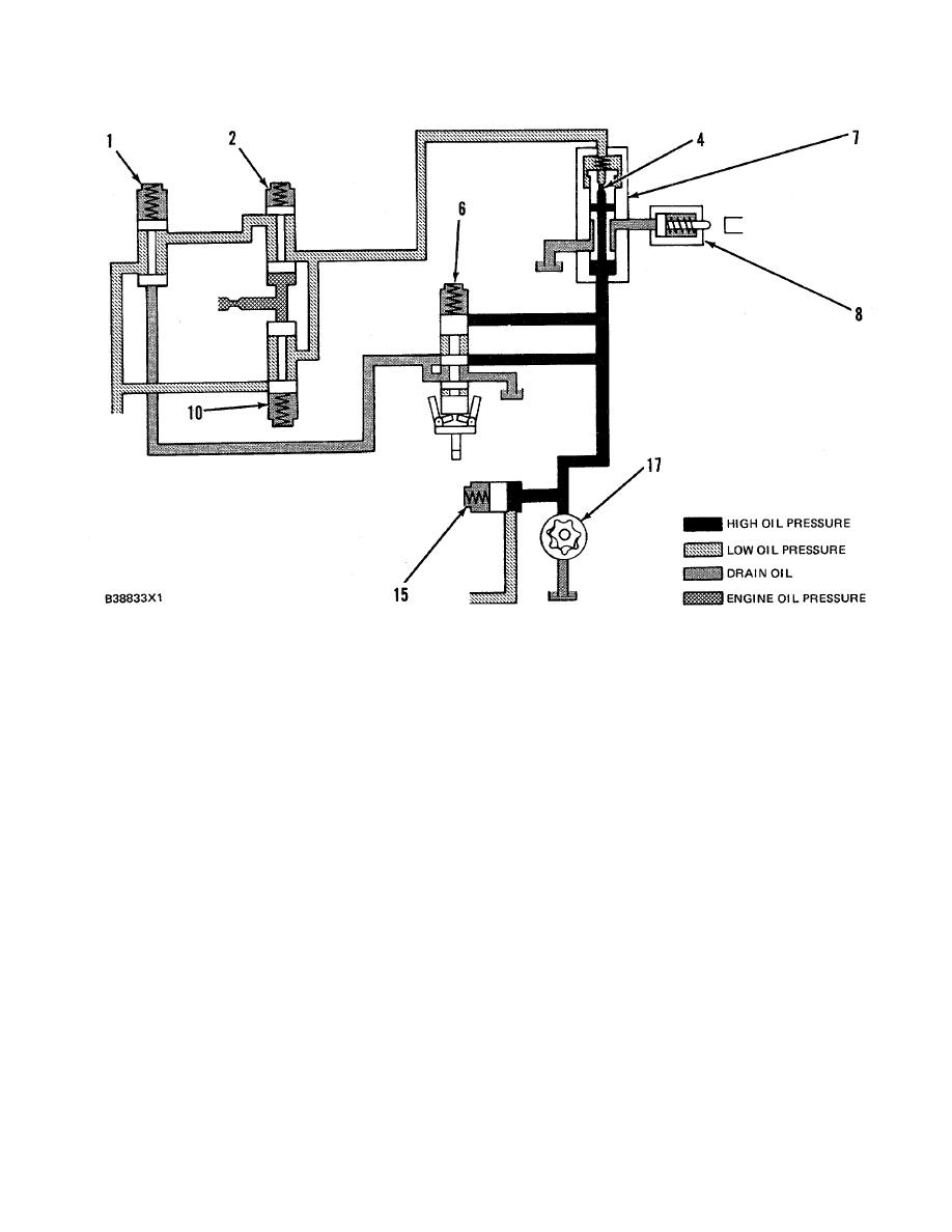 HYDRAMECHANICAL PROTECTIVE SYSTEM
SYSTEMS OPERATION
SCHEMATIC NO. 2 (LOW ENGINE OIL PRESSURE CIRCUIT)
(Low Speed Range)
1. Selector valve. 2. Low speed oil protection valve. 4. Diverter valve orifice. 6. Speed sensing valve spool. 7.
Diverter valve. 8. Fuel shutoff actuator. 10. High speed oil protection valve. 15. Fuel shutoff sequence valve.
17. Oil pump.
LOW SPEED RANGE (NORMAL ENGINE OIL
PRESSURE)
At diverter valve (7), the oil flows through orifice
Make Reference to Schematic No. 2
(4) which causes a pressure difference across both ends
of the valve spool. The valve spool is then moved by
When an engine is started and speed increases,
system oil pressure, against a spring force, to keep the
engine oil pressure moves low speed oil protection valve
fuel shutoff actuator from being operated. The oil then
(2) open. At the same time, oil in the protective system
flows from diverter valve (7) to drain through low speed
flows from oil pump (17) to fuel shutoff sequence valve (
oil protection valve (2) and selector valve ( I ).
15) and diverter valve (7). Fuel shut- off sequence valve
(15) keeps the inlet pressure to diverter valve (7) at 760
NOTE: Engine oil pressure is not high enough at this
kPa (110 psi) and then directs the remainder of oil flow
through the air inlet shutoff circuit. Most of the air inlet
point to move valve (10) against the force of the spring.
shutoff circuit has been left out since it is not directly in
use at this point.
216
|
||
|
||


