
| Tweet |

Custom Search
|
|

|
||
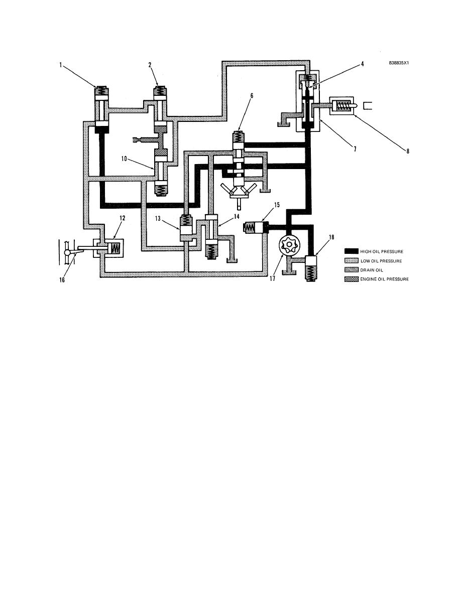 HYDRAMECHANICAL PROTECTIVE SYSTEM
SYSTEMS OPERATION
SCHEMATIC NO. 4 (LOW ENGINE OIL PRESSURE CIRCUIT)
(High Speed Range)
1. Selector valve. 2. Low speed oil protection valve. 4. Diverter valve orifice. 6. Speed sensing valve spool. 7.
Diverter valve. 8. Fuel shutoff actuator. 10. High speed oil protection valve. 12. Air inlet shutoff actuator. 13.
Air inlet sequence valve. 14. Pilot operated two-way valve. 15. Fuel shutoff sequence valve. 16. Air inlet shutoff
valve. 17. Oil pump. 18. Oil pressure relief valve.
HIGH SPEED RANGE (NORMAL ENGINE
OIL PRESSURE)
Make Reference to Schematic No. 4
At approximately 70% of engine full load speed,
the oil pressure protection changes from the low
speed range to the high speed range. At this
point engine oil pressure is high enough to open
high speed oil protection valve (10).
System oil flow to diverter valve (7) is the same
as it is for the low speed range except speed
sensing valve spool (6) has been shifted. When
the engine speed increases to the high speed
range, speed sens- ing valve spool (6) will be
moved up by the fly- weights. This directs system
oil pressure at 760 kPa (110 psi) to selector valve
(1). The valve closes toL/ remove low range oil
pressure protection valve (2) from the circuit. The
oil now flows from diverter valve (7) to drain
through high speed oil protection valve (10) and
pilot operated two-way valve (14).
218
|
||
|
||


