
| Tweet |

Custom Search
|
|

|
||
 HYDRAMECHANICAL PROTECTIVE SYSTEM
SYSTEMS OPERATION
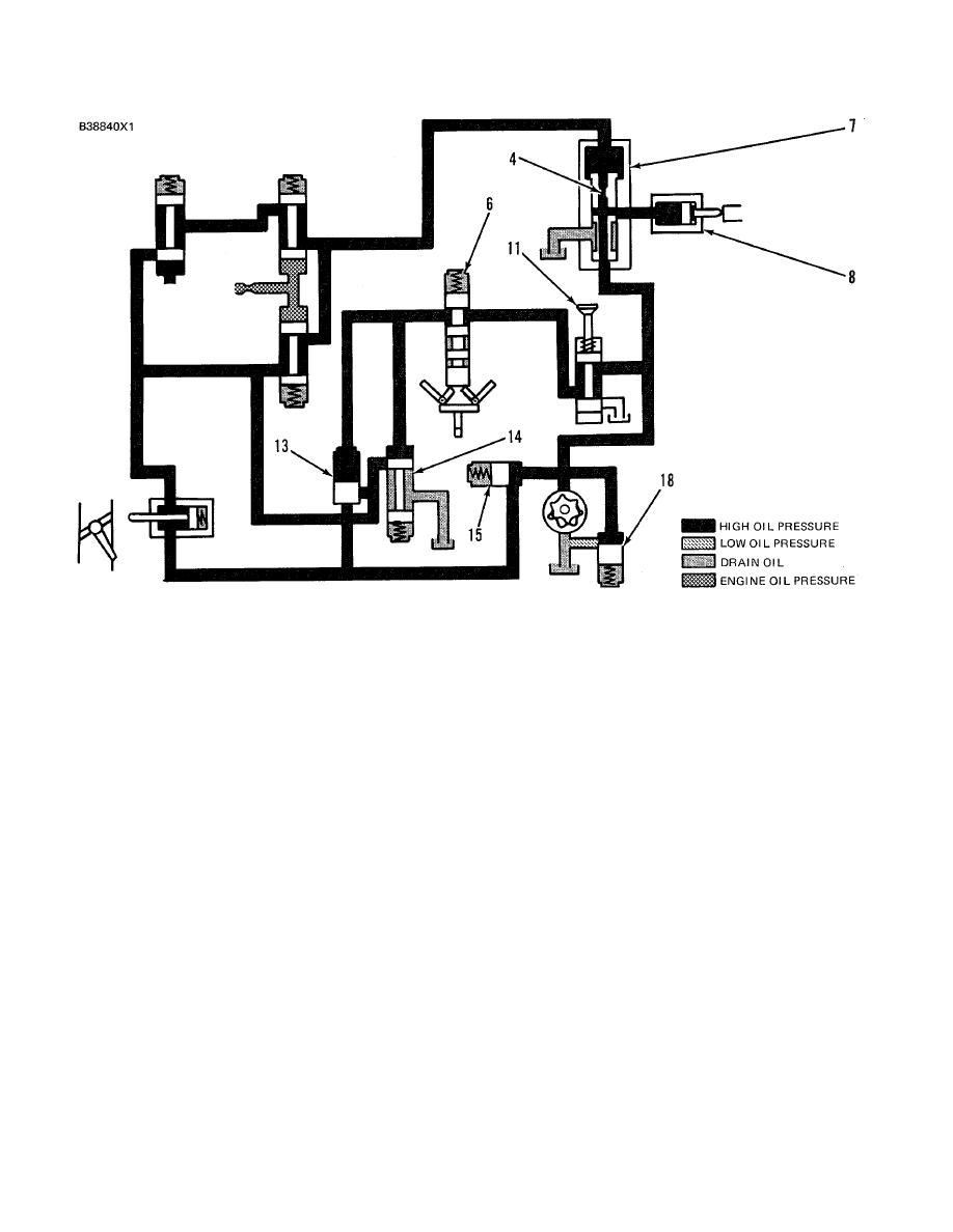
SCHEMATIC NO. 10 (EMERGENCY MANUAL SHUTOFF)
4. Diverter valve orifice. 6. Speed sensing valve spool. 7. Diverter valve. 8. Fuel shutoff actuator. 11.
Emergency manual shutoff valve. 13. Air inlet sequence valve. 14. Pilot operated two-way valve. 15. Fuel
shutoff sequence valve. 18. Oil pressure relief valve.
EMERGENCY MANUAL SHUTOFF
Make Reference to Schematic No. 10
When the knob on emergency manual shutoff (
11 ) is pulled, system oil flow is directed to pilot
operated two-way valve (14) to close the valve.
This stops oil flow to drain in both the fuel and air
inlet shutoff circuits. The protective system then,
shuts down the engine in the same sequence as
for an overspeed fault condition.
The
combustion air supply is stopped and the fuel
control linkage is moved to the "SHUT- OFF"
position to shutdown the engine.
225
|
||
|
||


