
| Tweet |

Custom Search
|
|

|
||
 HYDRAMECHANICAL PROTECTIVE SYSTEM
SYSTEMS OPERATION
LATER HYDRAULIC CIRCUITS WITH AN
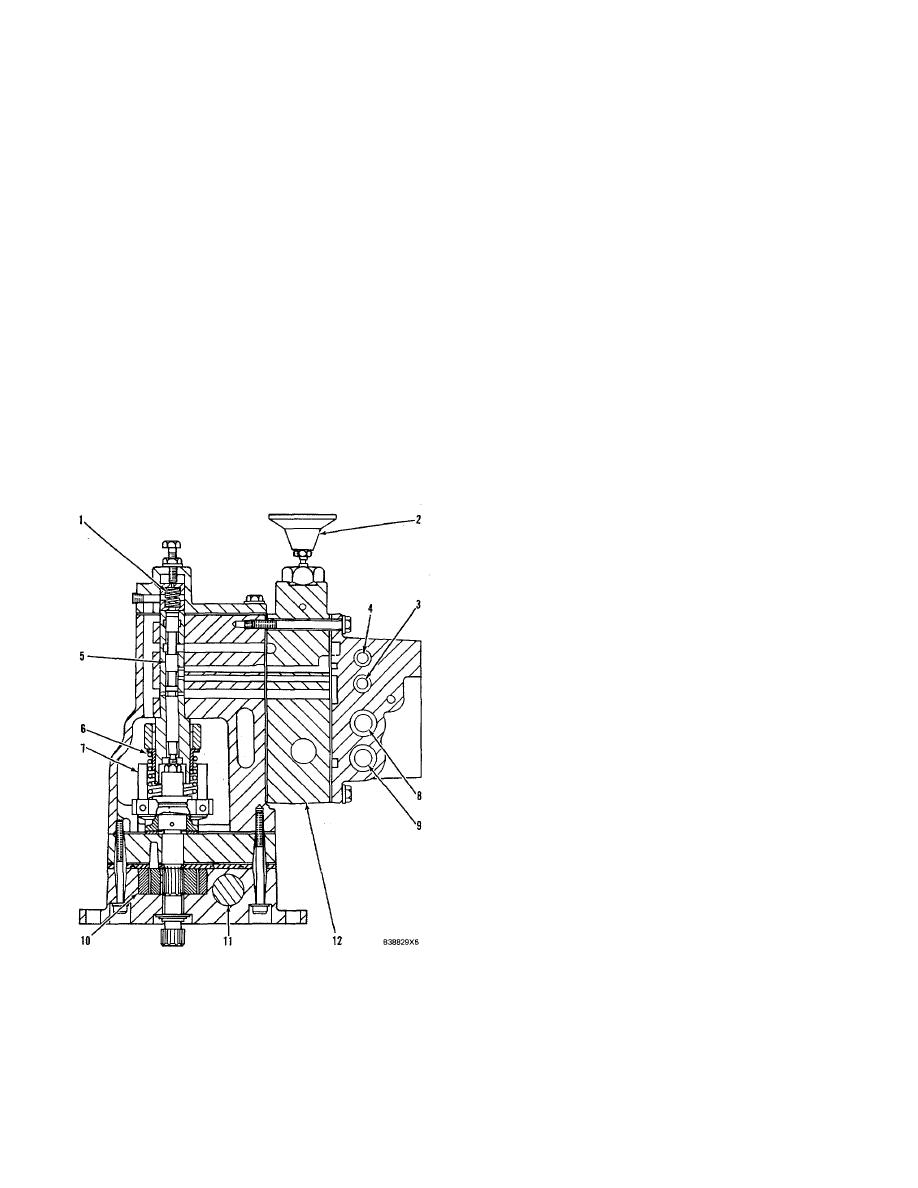
10. Oil pump. 11. Oil pressure relief valve. 12.
ALARM SYSTEM
Pressure control valve group which consists of: the
fuel and air inlet sequence valves, the two-way pilot
This hydramechanical protective system is de-
operated valve and emergency manual shutoff valve
signed to give automatic engine shutdown from an
(2).
overspeed condition only. An alarm is activated for low
engine oil pressure and high coolant temperature
OVERSPEED CIRCUIT (NORMAL CONDITIONS)
conditions.
Make Reference to Schematic No. 16
The main difference between this system and
systems shown in the EARLIER and LATER
When an engine is started and speed increases,
HYDRAULIC CIRCUITS, is that the fuel shutoff circuit oil
engine oil pressure opens low speed oil protection valve
return from the diverter valve is connected with the air
(8) and high speed oil pressure protection valve (9). At
inlet shutoff circuit return, and not to the normal fuel
the same time, oil in the protective system flows from oil
shutoff return port on the shutoff control group. A
pump (10) to fuel shutoff sequence valve (24) and is
normally open pressure switch (13) is in- stalled in the
divided between the fuel shutoff and air inlet shutoff
shutoff control group at the location the diverter valve oil
circuits. Fuel shutoff sequence valve (24) keeps the oil
return line is normally connected. Also, there is an orifice
pressure at the start of the fuel shutoff circuit at 760 kPa
plug [orifice (14)] installed in the shutoff control group.
(110 psi).
The orifice plug is located in the valve body that holds
valves (4), (8) and (9). In the hydraulic circuit, this orifice
Oil in the air inlet shutoff circuit is directed to air
is between the oil pressure supply and the low and high
inlet sequence valve (22) and air inlet shutoff actuator
oil pressure protection valves (8) and (9).
(26). Air inlet sequence valve (22) keeps the oil pressure
in air inlet shutoff actuator (26) at 105 kPa ( 15 psi) and
then directs the remainder of oil flow to drain through
pilot operated two-way valve (23) which is normally open.
Pilot operated two-way valve (23) is held open by spring
force and the pilot oil pressure is connected to drain
through speed sensing valve spool (5).
Oil flow in the fuel shutoff circuit is divided into
different directions as follows:
1.
Oil from fuel shutoff sequence valve (24) goes to
speed sensing valve spool (5) and is stopped at
low engine speeds. When engine speed is high
enough, speed sensing valve spool (5) moves to
direct the oil pressure and close selector valve
(3). This changes the oil flow in the alarm circuit
from the low speed range to the high speed
range and connects system oil pressure to drain
through high speed oil protection valve (9) and
pilot operated two-way valve (23).
2.
Oil flow from fuel shutoff sequence valve (24)
goes through orifice (14), low speed oil protec-
tion valve (8) or high speed oil protection valve
(9) and to drain through pilot operated two-way
valve (23). This circuit has an oil pressure
switch (13), that is normally open. Switch (13) is
connected to the alarm circuit oil pressure after
orifice (14) and senses the lower system oil
SHUTOFF CONTROL GROUP
pressure. The switch activates an alarm, without
1. Spring for overspeed adjustment. 2. Emergency
engine shutdown, if there is a low engine oil
pressure or high coolant temperature condition.
manual shutoff valve. 3. Selector valve. 4. Valve
(Make reference to Schematic No. 18).
spool (not used). 5. Speed sensing valve spool. 6.
Speeder spring. 7. Flyweights. 8. Low speed oil
protection valve. 9. High speed oil protection valve.
232
|
||
|
||


