
| Tweet |

Custom Search
|
|

|
||
 3500 ENGINES
DISASSEMBLY AND ASSEMBLY
HYDRAMECHANICAL SHUTOFF CONTROL
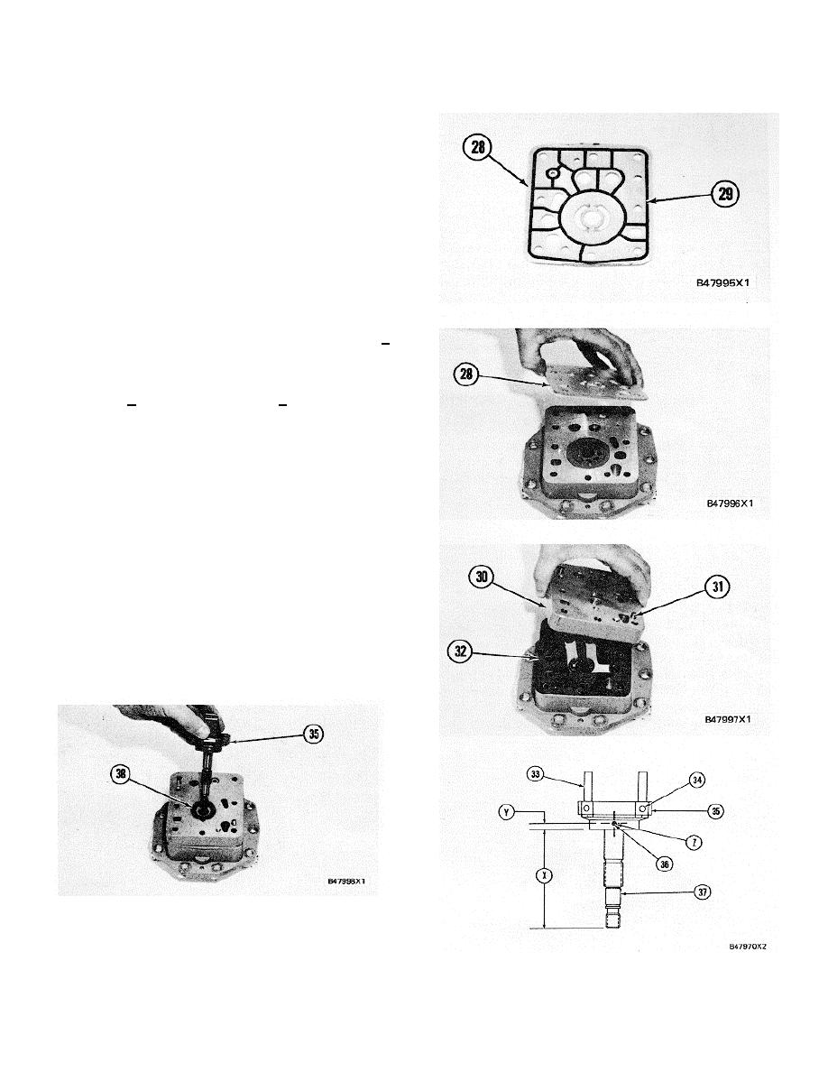
10.
Install seal (29) on plate (28) and put clean
engine oil on it.
11.
Install plate (28) on the housing assembly.
12.
If necessary, make a replacement of dowels
(31) and make sure they are 6.5 + 0.5 mm (.256
+ .020 in.) above the surface of the cover
assembly.
13.
Put gasket (32) in position and install-cover
assembly (30) on the plate.
14.
Use a press to install shaft (37) in carrier (35)
until dimension (X) is 84.08 + 0.25 mm (3.310 +
.010 in.).
NOTE: If either or both the shaft and the carrier are new,
a hole 3.175 + 0.051 0.000 mm (.125 + .002 .000 in.) in
diameter must be drilled through either or both the shaft
and the carrier at location (Z) and dimension (Y) must be
5.0 + 0.5 (.197 + .020 in.). This must be done before
Step 15 can be done.
15.
Install pin (36) to hold the shaft and carrier in
position.
16.
Put weights (33) in position on carrier (35) and
install dowels (34) to hold the weights. Each
weight must move freely on its dowel and must
have 0.02 to 0. 18 mm (.001 to .007 in.) end play
after assembly. Put marks (counter punch) four
places around both ends of the dowels.
17.
Install washer (38) on the cover assembly and
put carrier assembly (35) in position in the
gerotor pump group.
342
|
||
|
||


