| Tweet |

Custom Search
|
|

|
||
 3500 ENGINES
DISASSEMBLY AND ASSEMBLY
FUEL INJECTORS
the correct adjustment of the fuel injection of the
INSTALL FUEL INJECTORS
1251-12
fuel injection control group. Make sure the
control group can move to the fuel off position
Tools Needed
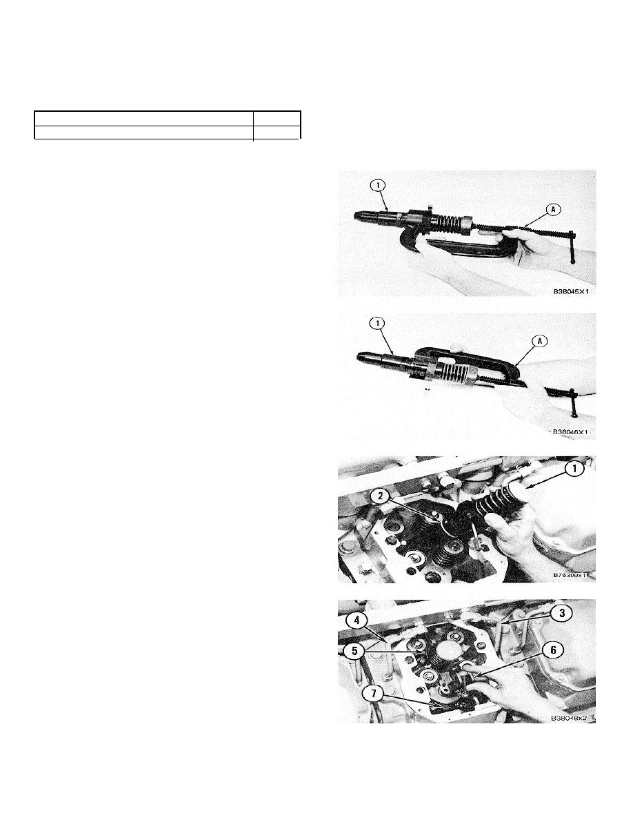
A
with the governor linkage disconnected.
6V4062
Injector Spring Compressor
1
end by:
a) install rocker shafts and push rods
1.
Use tool (A) as shown to make sure the fuel
injection rack will move freely by its own weight
when injector (1) is turned a total of. 180 in
both directions. Check the rack movement with
the injector spring under compression. in several
positions.
NOTE: To prevent a carbon deposit between the injector
and the injector bore, make sure the injector body
(especially the tapered area) and the injector bore are
clean and free of foreign material.
2.
Make sure the three O-ring seals (2) are
installed on injector (1) and put clean engine oil
on the seals and in the bore for the injector.
3.
Make sure the plug that the anvil of clamp (5)
sets on is installed in the top of the cylinder
head.
NOTICE
Do not tap or hit on the injector
follower to install the injector.
Damage and failure of the injector
can be the result.
4.
Put injector (1) in position in the cylinder head.
Install clamp (5) and tighten the bolt and washer
to push injector (1) all the way into its bore.
Tighten the bolt to a torque of 65 7 Nm (48
5 lb.ft.).
5.
Check to make sure the fuel injection rack
moves freely by hand in the injector after the
injector is installed.
6.
Put lever assembly (6) in position. Connect the
lever assembly to control rod (7) and make sure
lever assembly (6) is engaged correctly with the
fuel injection rack. Install the two bolts to
holdB7. the lever assembly in place.
7.
Remove the caps from the fuel openings and
install inlet fuel tube (3) and outlet fuel tube (4)
on the cylinder head. Open the fuel supply to the
engine.
8.
See TESTING AND ADJUSTING section for
370
|
||
 |
||