
| Tweet |

Custom Search
|
|

|
||
 3500 ENGINES
DISASSEMBLY AND ASSEMBLY
CRANKSHAFT MAIN BEARINGS
follows:
NOTICE
If the crankshaft is turned in the wrong direction, the
tab of the bearing will be pushed between the
crankshaft and cylinder block. This can cause
damage to either or both.
NOTE: On the center main journal that has no oil hole,
put a thin piece of soft material that will not damage the
crankshaft journal against the end of the bearing,
opposite the tab. Hit the bearing with the soft material
until the tab of the bearing is free from the cylinder block.
Remove the upper half of the main bearing.
9.
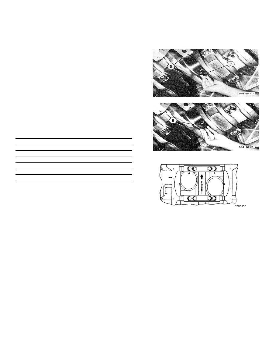
Install tool (C) in the oil hole in the crankshaft
journal and remove upper main bearing halves
(5) as the crankshaft is turned and the bearing is
moved out of the cylinder block.
INSTALL CRANKSHAFT MAIN
BEARINGS
1203-12
Tools Needed
ABCD
9S9082 Engine Turning Pinion 1
2P5517 Bearing Removal and
Installation Tool
1
8S2328Dial Test
Indicator Group
1
6V3147 Main Bearing Wrench
1
NOTICE
Make sure the upper and lower halves of bearings
are installed so the bearing tabs fit into the notch in
cylinder block and bearing caps.
checks are made. Put clean engine oil on the main
a)
Put a piece of the Plastigage on the surface
bearings for final assembly.
of the lower bearing half.
b)
Install the main bearing caps with the word
1.
Install tool (B) in the oil hole of the crankshaft.
"FRONT" and the cast part number toward
Put the upper bearing half (half with oil hole) in
the front of the cylinder block. Each cap
position on the crankshaft. Use tool (A) to turn
has a number on the bottom surface and
the engine flywheel and push the bearing half in
must be installed in the same position as
position with tool (B).
the correct number on the right side of the
2.
Make sure the bearing caps are clean and install
block pan rail.
the lower bearing halves in the caps.
c)
Put clean engine oil on the main bearing
NOTICE
cap bolts and tighten them in the number
Do not use an impact wrench to tighten the
sequence shown with tool (D) to a torque of
bolts the additional 180 5 of a turn more.
136 14 N.m (100 10 Ib.ft.). Then
NOTE: When the bearing clearance is checked and the
tighten the bolts in the number sequence
engine is in a vertical position, such as in the vehicle, the
shown 180 5 of a turn more.
crankshaft will have to be lifted up and held against the
d)
Remove the caps and measure the
upper halves of the main bearings to get a correct
Plastigage. The main bearing clearance
measurement with the Plastigage. The Plastigage will
must be 0.122 to 0.241 mm (.0048 to .0095
not hold the weight of the crankshaft and give a correct
in.).
indication. If the engine is in a horizontal position, it is
not necessary to hold the crankshaft up. Do not turn the
crankshaft when the Plastigage is in position to check
clearances.
3.
Check the bearing clearances with Plastigage as
394
|
||
|
||


