| Tweet |

Custom Search
|
|

|
||
 3500 ENGINES
DISASSEMBLY AND ASSEMBLY
CYLINDER LINERS
REMOVE CYLINDER LINERS
1216-11
Tools Needed
A
5P8665
Cylinder Liner Puller
1
6V4133
Wedge Bracket
1
start by:
a) remove pistons
1.
Drain the coolant from the cooling system and
cylinder block.
2.
Put covers on the crankshaft journals for
protection from dirt and coolant.
3.
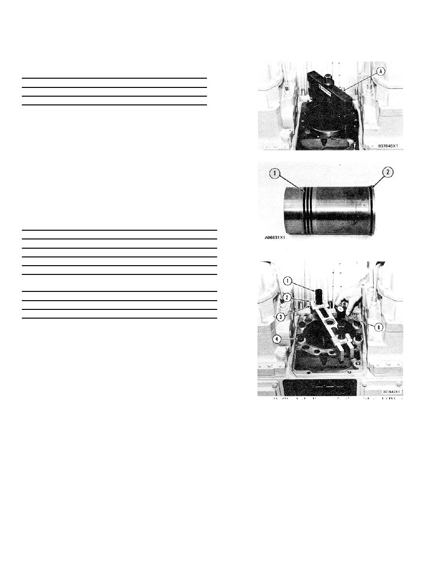
Remove the cylinder liner with tool (A).
4.
Remove seals (I) and filler band (2) from the
cylinder liner.
INSTALL CYLINDER LINERS 1216-12
Tools Needed
A
B
C
8B7548 Puller Assembly (Crossbar)
1
3H465
Plate
2
8F6123 Bolt (Y4"-16 NF x 5 /2 in. long)
2
3B1925 Washer (3/4"-Copper)
4
S1575
Bolt (3/4"-16 NF x 3 in. long)
4
1P5510 Liner Projection Tool Group
1
2P8260 Liner Installation Group
1
7N1961 Bolt (from Cylinder head)
1
FT1543 Plate
1
1.
Install the gasket and spacer plate.
2.
Clean the cylinder liners and liner bores in the
cylinder block.
3.
Install the cylinder liners in the cylinder block
without seals or bands.
4. Check the cylinder liner projection as follows:
d) Check the liner projection with tool (B) at
a) Install four bolts (4) and washers from
four locations around the liner.
Liner
tooling (A) around each cylinder liner as
projection must be 0.059 to 0.199 mm
shown. Tighten the bolts evenly to a torque
(.0023 to .0078 in.). The difference between
of 95 N-m (70 lb. ft.).
the four measurements on the same liner
b) Install crossbar (2), plates (3) and bolts (I )
must not be more than 0.05 mm (.002 in.).
from tooling (A). Be sure the crossbar is in
NOTE: If the liner is turned in the cylinder block, it can
position at the center of the liner and the
make a difference in liner projection.
liner surface is clean. Tighten bolts (1)
evenly to a torque of 70 N-m (50 lb. ft.).
c) Check the distance from the bottom edge of
crossbar (2) to the top edge of the spacer
plate. The distance on each end of the
crossbar must be the same.
398
|
||
 |
||