
| Tweet |

Custom Search
|
|

|
||
 ELECTRIC PROTECTIVE SYSTEM
SYSTEMS OPERATION
SYSTEM TROUBLESHOOTING CHARTS
toggle switch to control the electric starter motor
magnetic switch (install the switch in series with
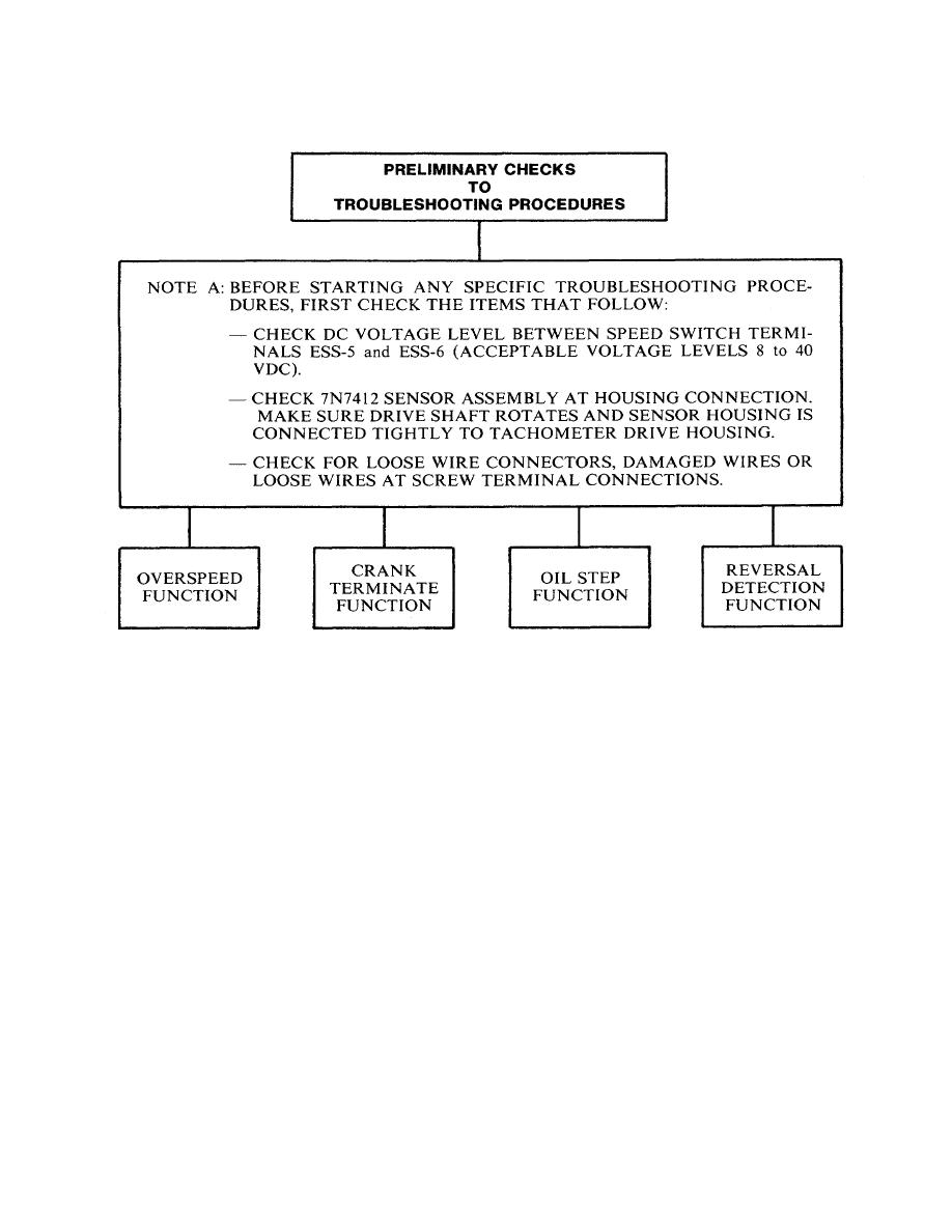
NOTE B:
Do Not Leave Starter Motor Engaged With
the magnetic switch coil lead).
Engine Running. Engines that have electric
starter motor(s), or a DC actuated air
3.
Manually disengage by installing a toggle
starter motor, automatically disengage
switch to control the air starter solenoid
when crank termination rpm is reached.
valve (install the switch in series with either
Positive (+) battery voltage is removed from
of the solenoid valve leads).
the engine mounted or remote mounted
starter controls when the normally closed
crank termination contacts open.
To
perform test measurements, one of the
methods that follow may be necessary to
NOTE: For wiring diagrams and schematics, make
disengage the starter motor:
reference to Wiring Diagrams Section.
1.
Disconnect wire
at
speed
switch
terminal ESS-12.
2.
Manually disengage by installing a
487
|
||
|
||


