| Tweet |

Custom Search
|
|

|
||
 ELECTRIC PROTECTIVE SYSTEM
TROUBLESHOOTING
PROCEDURE A
5N1955 ELECTRONIC SPEED SWITCH
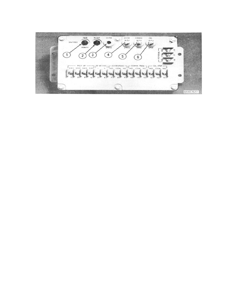
1. Verify button. 2. Reset button. 3. "LED" overspeed light. 4. Seal screw plug (overspeed). 5. Seal
screw plug (crank terminate). 6. Seal screw plug (oil step).
(counterclockwise) slowly until "LED" overspeed
OVERSPEED SETTING CALIBRATION
light (3) comes on. Engine will shutdown if
speed switch is connected to the fuel shutoff
1.
Remove lockwire and seal from seal screw plugs
solenoid and/or air inlet shutoff solenoid.
(4), (5) and (6). Remove seal screw plug (4)
from access hole for overspeed adjustment
5.
To reset speed switch, push in reset button (2).
screw.
Air inlet shutoff must be manually reset.
2.
Use a small screwdriver and lightly turn
6.
Slowly turn overspeed adjustment potentiometer
overspeed adjustment potentiometer twenty
approximately one turn clockwise and do Steps
turns in the direction of "MAX ARROW"
3, 4 and 5 again.
(clockwise).
NOTE: More adjustment may be needed to get the
NOTE: The overspeed adjustment screw is made so
correct setting.
Turn adjustment potentiometer
that it can not cause damage to the potentiometer, or be
clockwise
to
increase
speed
setting,
and
removed, if the adjustment screw is turned too many
counterclockwise to decrease speed setting.
Turn
turns in either direction.
adjustment potentiometer very slowly only a small
amount at a time until adjustment is correct.
3.
Run engine at 75% of desired overspeed setting
rpm.
Make reference to the SPEED
7.
When the speed setting is correct, install seal
SPECIFICATION CHART (Part of PROCEDURE
screw plug (4) in overspeed adjustment access
D).
hole. Tighten screw to a torque of 0.20 0.03
Nm (2 .3 lb. in.). Install the lockwire and seal
4.
With engine at 75% of overspeed setting rpm,
push VERIFY button (1) and hold in. Turn
(if crank termination and oil step adjustments are
overspeed adjustment potentiometer in the
complete).
direction
opposite
of
"MAX
ARROW"
496
|
||
 |
||