
| Tweet |

Custom Search
|
|

|
||
 ELECTRIC PROTECTIVE SYSTEM
TROUBLESHOOTING
PROCEDURE F
7N7412 SENSOR ASSEMBLY VERIFY
A.
Slowly turn the shaft of 7N7412 Sensor
Assembly
(2)
one
full
turn
in
a
NOTE : For bench testing, connect a voltage source with
a range from 8-40 VDC (24 VDC preferred) across the
counterclockwise direction [as viewed from
electronic speed switch (ESS) terminals ESS-5 and
drive end (4)]. and watch the voltage indication.
ESS-6. Terminal ESS-5 is the battery negative terminal,
A 4 to 6 VDC reading should be seen for all but
and ESS-6 is the battery positive terminal.
one small area of the shaft rotation. Mark the
position of the shaft where the voltage reading
was zero volts. This point is called SW1 00
reference point.
NOTE : If no voltage is indicated between terminal SW1
(ESS-1) and terminal ESS-5 through one full turn of the
sensor shaft rotation, check speed switch for proper
voltages. A voltage of 4 to 6 VDC should be seen across
terminals ESS-4 and ESS-5. If speed switch voltage is
correct, then either the sensor is defective or the wiring
from the sensor to the speed switch is defective.
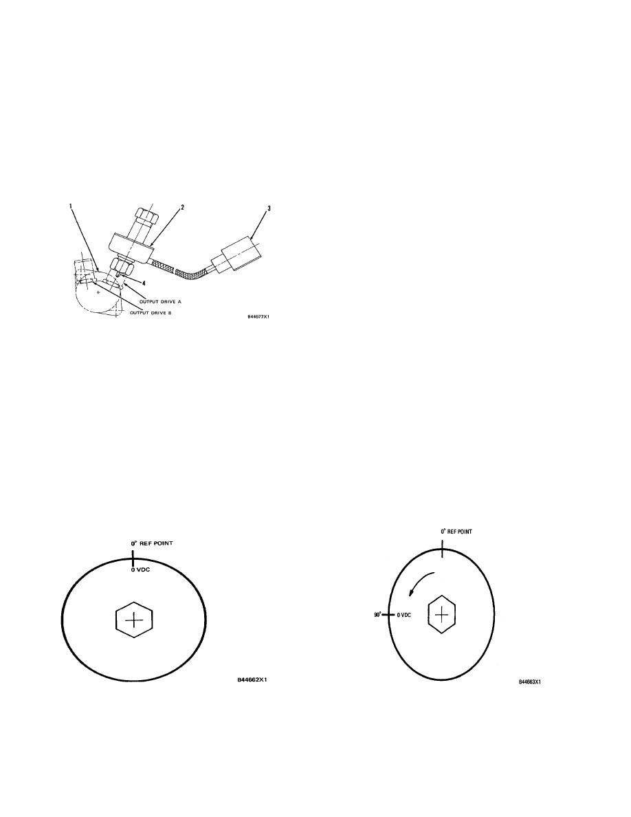
After finding SW1 0 reference point (the position
INSTALLED SENSOR ASSEMBLY
(Position shown is for RH rear of engine)
where zero voltage was measured on the sensor), an
1. Tachometer drive housing. 2. 7N7412 Sensor
additional zero volts indication will be measured once for
every 900 of shaft rotation from the 0 reference point by
Assembly. 3. Sensor harness connector. 4. Sensor
drive end.
using the sequence that follows:
B.
Connect the positive (+) voltmeter lead to SW2
1.
Disconnect 7N7412 Sensor Assembly (2) from
(ESS-2) and leave the negative (-) voltmeter lead
engine tachometer drive housing (1). Set the
voltmeter (6V3030 Multimeter or a voltmeter of
connected to ESS-5. Now slowly turn the
same accuracy) voltage scale to a scale higher
sensor shaft counterclockwise. A 4 to 6 VDC
than 6 VDC. Connect the voltmeter to the 5N
reading should be seen for all but one small area
1955 Electronic Speed Switch with the positive
of shaft rotation at an interval 900 from the SW1
0
(+) voltmeter lead connected to SW1 (ESS-1)
reference point. Zero volts will be indicated at
and the negative (-) voltmeter lead connected to
this area.
terminal ESS-5 (-).
SW2 CHECK
SW1 CHECK
501
|
||
|
||


