| Tweet |

Custom Search
|
|

|
||
 ELECTRIC PROTECTIVE SYSTEM
TROUBLESHOOTING
PROCEDURE G
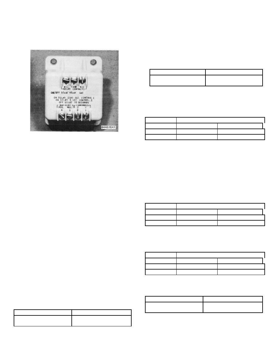
ON/OFF TIME DELAY (RELAY)
2.
(a)
Apply positive (+) source voltage to terminal
1 (either relay) and immediately verify the
chart that follows (do not leave voltage on
terminal 1 for more than 60 seconds):
Terminals
Relay Position
5
Open
7
Closed
(b) Remove positive (+) source voltage from
terminal 1. Use a stop watch and check the
time from the moment of removal to verify
chart that follows:
Terminals
Delay Time to Function
0 to 60 Secs.
After 80 Secs.
5
Open
Closed
7
Closed
Open
ON/OFF DELAY (RELAY)
3.
(a) Apply positive (+) source voltage to terminal
2.
NOTE: If bench testing, Step 3 can be used with either
relay. When installed on engine, Step 3 can only be
checked with TD2. Do not apply positive (+) voltage
to terminal 2 of TD1, or a direct short will result.
Performance Check (either TD1 or TD2 relays can be
checked with methods that follow)
Check the time from the moment voltage is
applied to verify chart that follows (do not leave
A.
Items Required For Check:
voltage on terminal 2 for more than 60 seconds):
1. Battery or any D. C. source of 8 to 40 volts.
Terminals
Delay Time to Function
2.
Voltmeter (6V3030 Multimeter or one of
0 to 8 Secs.
After 10 Secs.
same accuracy).
5
Closed
Open
7
Open
Closed
3.
Stop watch.
(b) Remove positive (+) source voltage from
B.
Bench Or Installed Test
terminal 2. Check the time from the moment
of removal to verify chart that follows:
Connect or verify source voltage to relay
terminals 3 (-) and 4 (+) [if bench testing, also connect
positive (+ ) voltage to relay terminal 6]. All connections
Terminals
Delay Time to Function
must be maintained until tests are complete.
0 to 60 Secs.
After 80 Secs.
5
Open
Closed
NOTE: There will be voltage when the relay is closed.
7
Closed
Open
When relay is open, there will be no voltage [voltage may
be positive (+) or negative (-) when relay is tested on
4. Remove wire from terminal 4 and verify chart that
engine; when bench testing, voltage will always be
follows:
positive (+)].
Terminals
Relay Position
1. Use the voltmeter to verify chart that follows:
5
Closed
2.
7
Open
Terminals
Relay Position
5
Closed
7
Open
503
|
||
 |
||