TM 5-2815-241-34&P
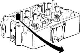
CYLINDER HEAD - CONTINUED
ACTION
LOCATION
ITEM
REMARKS
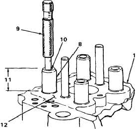
17.
Valve guide (8)
a.
Inspect for chips, cracks, burrs, or
broken sections.
If chipped, cracked, or broken, or
burrs are found, tag valve guide
for replacement. See step 23.
b.
Set dial bore gage (9) at 0.4552 inch
(11.562 mm). Attempt to insert gage
into valve guide bore (10).
If gage goes into bore, tag valve
guide for replacement. See step 23.
c.
Check for out-of-round bores.
If bore is out of round, tag valve
guide for replacement. See step 23.
d.
Check valve guide protrusion (11) from
cylinder head surface (12).
If protrusion is less than 1.315
inches (33.43 mm), tag valve guide
for replacement. See step 23.
T A 2 4 2 4 5 8
2-185
|
|