TM 5-2815-241-34&P
CYLINDER HEAD - CONTINUED
ACTION
LOCATION
ITEM
REMARKS
REPAIR/ASSEMBLY - CONTINUED
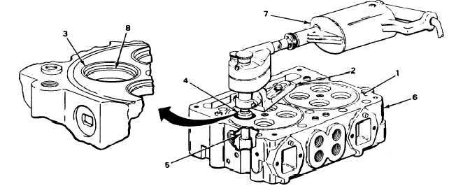
29. Cylinder head
mating surface (1)
a.
Clamp base of ST-663 valve guide
arbor set (2) to cylinder head mating
surface near valve seat insert
bore (3).
b.
Center ST-662 valve seat insert cutter
(4) in valve seat insert bore (3) and
on ST-1217 valve guide mandrel (5).
After tool assembly is centered, be
sure tool assembly Is securely
clamped to cylinder head.
NOTE
To ensure a perfectly flat bottom of bore for valve seat inserts to seat correctly, allow
cutter to turn several revolutions at exact moment the proper depth in cylinder head is
reached.
30. Cylinder head (6)
Valve seat insert
bore (3)
Using ST-257 valve seat insert driver tool
(7), cut counterbore (8) 0.006 to 0.010
inch (0.1524 to 0.2540 mm) deeper than
insert thickness to allow staking of cylin-
der head to secure valve seat insert.
T A 2 4 2 4 6 8
2-196
|
|