TM 5-2815-241-34&P
CYLINDER HEAD - CONTINUED
ACTION
LOCATION
ITEM
REMARKS
REPAIR/ASSEMBLY - CONTINUED
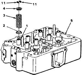
58. Valve guide (1)
Valve spring seat
(2), valve spring
(3), and valve spring
retainer (4)
Assemble onto valve guide.
WARNING
Extreme care must be taken when installing springs under pressure. Injury to personnel
could result.
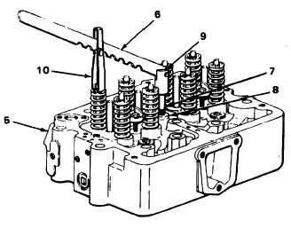
59. Cylinder head (5)
Valve spring
compressor (6)
a.
b.
c.
d.
Install stud (7) into rocker lever cap
screw hole (8).
Install valve spring compressor pivot
head (9) on stud (7).
Place compression head (10) on valve
spring retainer (4), press down valve
spring compressor, and install new half
collets (11).
Remove valve spring compressor and
stud (7) from cylinder head.
T A 2 4 2 4 8 0
2-210
|
|


