TM 5-2815-241-34&P
ROCKER ARM HOUSING AND PUSH ROD
This task covers:
a. Disassembly (page 2-242)
c. Inspection (page 2-245)
b. Cleaning (page 2-244)
d. Assembly (page 2-251)
INITIAL SETUP
Tools
Bit, drill, 9/32-inch
Driftpin, brass, 3/4-inch
Drill, electric, 3/8-inch
Gage, bore, dial
Gage, radius, 1/4-inch
Gage, radius, 5/16-inch
Goggles, safety
Hammer, ball-peen, 16-ounce
Key, hex, 5/32-inch
Mandrel and block, ST-691
Micrometer, 1- to 2-inch
Press, arbor
Punch, pin, 1/4-inch
Screwdriver, flat-tip, 3/8-inch
Wrench, box-end, 7/16-inch
Wrench, box-end, 3/4-inch
Materials/Parts
Bushing, rocker arm (as required)
Cloth, emery (item 1, appendix B)
Locknut (six required)
Oil, lubricating (Item 12, appendix B)
Packing, preformed (two required)
Prussian blue (item 13, appendix B)
Solvent, drycleaning (item 16, appendix B)
Tags, marker (item 17, appendix B)
Equipment Condition
Rocker arm housing removed (page 2-30).
References
TM 55-1500-335-23, Inspection Methods,
Non-Destructive
ACTION
LOCATION
ITEM
REMARKS
DISASSEMBLY
NOTE
Steps given are typical for all three rocker arm housings
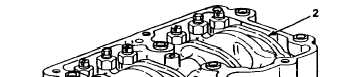
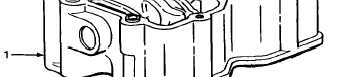
1. Rocker arm
housing (1)
Six rocker arms (2)
Tag and number rocker arms in sequence
1 thru 6 starting from front of rocker arm
housing.
2-242
Change 1
|
|