TM 5-2815-241-34&P
INTAKE MANIFOLD - CONTINUED
ACTION
LOCATION
ITEM
REMARKS
4.
Glow plug and pre-
Glow plug (6) and
Inspect for stripped threads, cracked
heater assembly (4)
preheater nozzle (7)
porcelain or cracked preheater nozzle.
If stripped or cracked, replace.
ASSEMBLY
5.
Glow plug and pre-
Glow plug (6) and
a.
Using 7/8-inch box-end wrench, screw
heater assembly (4)
preheater nozzle (7)
in glow plug and tighten.
b. Using 1 1/4-inch box-end wrench,
screw in preheater nozzle and tighten.
6. Intake manifold (1)
New gasket (5) and
glow plug and pre-
heater assembly (4)
Place in position.
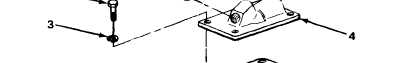
7.
Glow plug and pre-
Five screws (2)
Using 9/16-inch box-end wrench, install
heater assembly (4)
and five new
and tighten.
lockwashers (3)
NOTE
FOLLOW-ON MAINTENANCE:
Install intake manifold (page 2-119).
TASK ENDS HERE
2-275
|
|