*C2
*C2
C H A P 5, SEC II
D I S A S S E M B LY
P A R 74, STEPS 1 - 4
7 4 . D I S A S S E M B L Y S T E P S
-
I N P U T T R A N S F E R A S S E M B LY
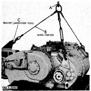
Figure 39 (Step 1)
U s i n g h o i s t ( A ) , s l i n g ( B ) , a n d b r a c k e t ( C ),
position the power train assembly on blocks
( D ) o n t h e f l o o r o r d i s a s s e m b l y t a b l e , R e-
move the sling and bracket.
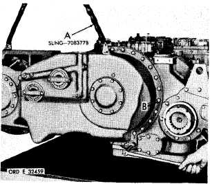
Figure 40 (Step 2)
Remove input transfer assembly (A) and gas-
Attach sling (A) to the input transfer housing.
U s i n g a 5 / 8 - i n c h w r e n c h , r e m o v e 1 6 i n p ut
t r a n s f e r - t o - c o n v e r t e r h o u s i n g b o l t s a n d l o ck
washers (B).
7
8
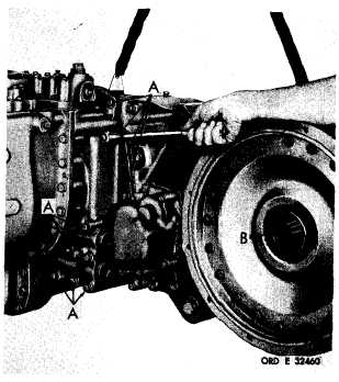
Figure 41 (Step 3)
U s i n g a 5 / 8 - i n c h w r e n c h , r e m o v e 1 0 i n p u t
transfer-to-converter
housing
bolts
and
10 lock washers (A). Remove engine coupling
shaft (B).
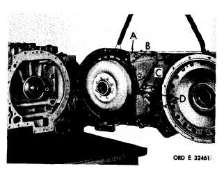
Figure 42 (Step 4)
k e t ( B ) . U s i n g a 9 / 1 6 - i n c h w r e n c h , r e m o v e
11 bolts and lock washers (C) retaining input
a n d s c a v e n g e o i l p u m p a s s e m b l y . I f n e c e s-
sary, use two mounting bolts as jackscrews,
in holes (D).
|
|