CHAP 5, S E C 1]
D I S A S S E M B LY
P A R 74, S T E P S 1 7 - 2 0
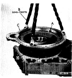
Figure 55 (Step 17)
Install three mounting bolts (A) in jackscrew
holes. Attach sling (B) and remove adapter (C)
and gear (D). Remove gasket (E). Caution:
While lifting adapter, be careful t o prevent
gear from dropping.
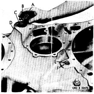
Figure 56 (Step 18)
If input transfer drive gear (A) remained with
flange adapter assembly (B), position the as-
sembly in a press. Press gear (A) and its
bearings, as an assembly, from the adapter.
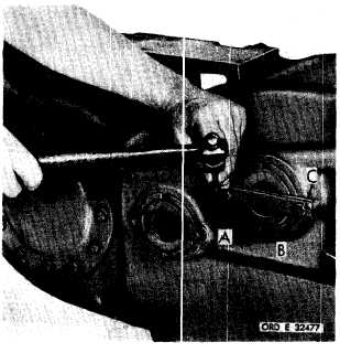
Figure 57 (Iltep 19)
Remove plug (,4), gasket (B) and oil screen ((C)
from input tramsfer h o IIs i n g (D). Using a
5/8-inch wrenc:h, remov(! self- locking bolt (E)
and flat washer (F).
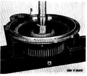
*m Figure 58 (f3tep 20)
Using a hammer and chisel, straighten lock
strip (A). Re:move two bolts (B), lock strip
(A) and strap (C).
82
|
|