P A R 7 5 S T E P S 3 - 6
D I S A S S E M B L Y
C H A P 5, SEC II
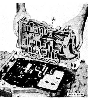
Figure 67 (Step 3)
R e m o v e r e g u l a t o r a n d l o c k u p s h i f t c o n t r ol
valve body oil transfer plate (A) and gasket (B).
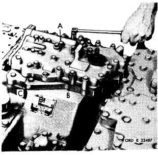
Figure 68 (Step 4)
Using a l/2-inch wrench, remove 28 bolts (A)
a n d l o c k w a s h e r s ( B ) r e t a i n i n g m a i n c o n t r ol
valve body assembly (C).
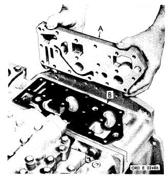
Figure 69 (Step 5)
Remove main control valve body assembly (A)
and gasket (B).
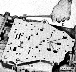
Figure 70 (Step 6)
U s i n g a l / 2 - i n c h w r e n c h , r e m o v e f o u r b o l ts
(A) and lock washers (B) and four self-locking
bolts (C) with flat washers retaining main con-
trol valve body oil transfer plate assembly (D).
8
5
|
|