*C2
C H A P 5, SEC I I
D I S A S S E M B L Y
P A R 76, S T E P S 6 - 9
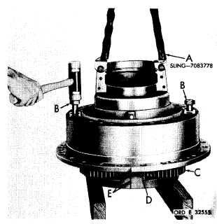
Figure 136 (Step 8)
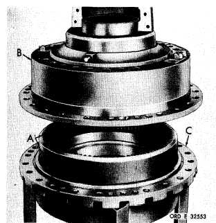
Figure 134 (Step 6)
Place an index mark (A) across output drive
s a d d l e ( B ) - t o - h o u s i n g ( C ) s p l i t l i n e . R e m o ve
saddle (B).
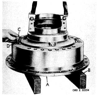
Figure 135 (Step 7)
Position output drive saddle assembly (A) on
w o o d e n b l o c k s ( B ) . R e m o v e r e m a i n i n g t wo
bolts (C) and washers (D).
Using sling (A) and two 7/8-14 x 6-inch bolts
(B), raise the assembly and drive output drive
p l a n e t a r y c a r r i e r ( C ) f r o m s a d d l e a s s e m b ly
(D). Place index marks (E) on the saddle and
c a r r i e r a s s e m b l y , t h e n r e m o v e s a d d l e a s-
sembly (D).
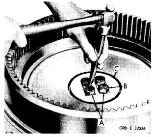
F i g u r e 1 3 7 ( S t e p 9 )
Straighten the tabs on lock strips (A). Using
a 1 5 / 1 6 - i n c h w r e n c h , r e m o v e f o u r b o l t s ( B ),
lock strips (A) and lock plate (C).
1 0 2
|
|