P A R 8 2 - 8 3
T O R Q U E C O N V E R T E R R E B U I L D
S e c t i o n I V . T O R Q U E C O N V E R T E R — R E B U I LD
C H A P 5, SEC I V
8 2 . D E S C R I P T I ON
Refer to p a r. 9 for description of the
t o r q u e c o n v e r t e r a s s e m b l y.
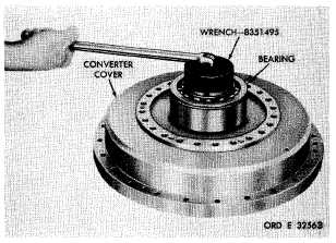
(5) Using spanner wrench 8351495, re-
move the converter lock nut (fig. 144).
(6) Remove the double-row ball bearing
from the hub of the converter cover.
83.
DISASSEMBLY (fig. 373, fold-out 2)
N o t e . All related items not covered
in a through d , below, were removed
from the transmission as outlined in
p a r . 7 4 , s t e p s 1 t h r o u g h 2 5 . No
f u r t h e r d i s a s s e m b l y o f t h o s e p a r t s
i s r e q u i r e d.
a . T o r q u e C o n v e r t e r C o v e r
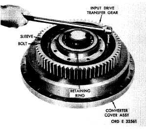
( 1 ) U s i n g a 5 / 8 - i n c h w r e n c h , r e m o ve
24 self-locking bolts retaining the input drive
t r a n s f e r g e a r ( f i g . 1 4 2 ) . R e m o v e t h e g e a r.
(2) Remove the retaining ring from the
torque converter support bearing .
(3) Remove the bearing support sleeve.
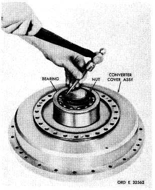
( 4 ) U s i n g a h a m m e r a n d p u n c h , b e nd
the lip of the converter lock nut away from the
n o t c h e s i n t h e h u b o f t h e t o r q u e c o n v e r t er
cover (fig. 143).
Figure 143. Straightening lip of torque converter
lock nut
Figure 142. Removing (or installing) input drive
transfer gear
Figure 144. Removing (or installing) converter lock nut
1
0
5
|
|