*C2
C H A P 5, SEC V
F L A N G E A D A P T E R R E B U I LD
PAR 8 6 - 91
(4) Install thrust washer 100 and front-
washer assembly 81. Install retaining ring 80.
( 5 ) I n s t a l l t h r u s t w a s h e r 1 0 3 i n t o t he
s t a t o r a s s e m b l y.
(6) Install thrust bearing assembly 102
o n t o f r e e w h e e l r a c e 1 0 1 , u s i n g o i l - s o l u b l e
grease to retain it.
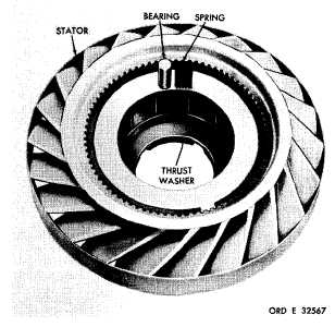
(7) Using a heavy oil-soluble grease to
r e t a i n t h e m , p o s i t i o n t h e 1 2 b e a r i n g s a n d
springs in the 12 stator cam pockets. Fig. 148
shows the location of the bearings and springs
i n r e s p e c t t o t h e s t a t o r a s s e m b l y . I n s t a l l a
spring into the deep end of the cam pocket.
Place a bearing in the shallow end of the cam
p o c k e t b e s i d e t h e s p r i n g . I n s t a l l r e m a i n i ng
11 bearings and springs in the same manner.
(8) Install freewheel race 101 (fig. 373,
fold-out 2) with bearing 102 into the stator as-
s e m b l y .
Figure 148. Torque converter stator
S e c t i o n V . F L A N G E A D A P T E R A S S E M B L Y — R E B U I LD
8 7 . D E S C R I P T I O N
R e f e r t o p a r . 8 f o r t h e d e s c r i p t i o n o f t h e
f l a n g e a d a p t e r a s s e m b l y .
8 9 . C L E A N I NG
Refer to par. 71 for cleaning recommend-
a t i o n s .
9 0 . I N S P E C T I O N A N D R E P A IR
R e f e r t o p a r . 7 2 f o r g e n e r a l i n s p e c t i on
and repair recommendations. Repair and re-
b u i l d p o i n t s o f m e a s u r e m e n t f o r f i t s , c l e a r-
ances and wear limits are indicated by small
letters in fig. 373, fold-out 2. Refer to par.
236 for wear limits information.
1
0
8
9 1 . A S S E M B L Y
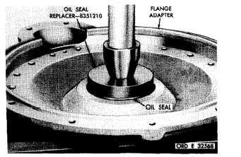
a . If the oil seal was removed from the
flange adapter, install a new replacement using
oil seal replacer 8351210 (fig. 149).
b . Install oil seal, lip side down, press-
i n g t h e s e a l u n t i l i t i s s e a t e d a g a i n s t i t s
shoulder in the adapter (fig. 149).
Figure 149. Installing oil seal in flange adapter
|
|