C H A P 5, SEC X V I II
R E A R H O U S I N G R E B U I LD
PAR 1 5 3
.
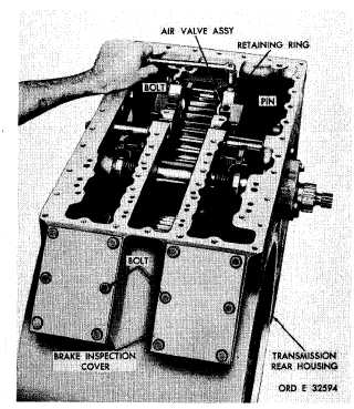
Figure 175. Removing transmission brake air valve
assembly
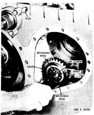
g . U s i n g a 9 / 1 6 - i n c h w r e n c h , r e m o v e
the shaft retaining cap screw (fig. 176). Using
a s l i d e h a m m e r r e m o v e r , r e m o v e t h e b r a ke
coolant pump idler gear shaft.
h . Using a square 5/16-inch wrench, re-
move the socket-head plug (fig. 176).
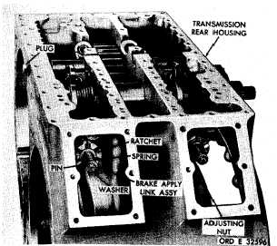
i. U s i n g 1 1 / 1 6 - i n c h w r e n c h , r e m o v e t he
hexagon-head plug (fig. 177).
j . Straighten the pin on each brake apply
link assembly and remove the pins, washers,
springs, ratchets and adjusting nuts (fig. 177).
k . R e m o v e t h e r i g h t - c a m f o l l o w e r l i n k
shaft (fig. 178).
l . R e m o v e t h e l e f t - c a m f o l l o w e r l i n k
shaft (fig. 178).
m.
Remove
the
left-cam
follower
and
brake apply link assembly (fig. 179).
n . R e m o v e r e t a i n i n g r i n g 1 4 ( f i g . 3 7 9,
fold-out 8) that retains pin 8 in left-cam fol-
lower link 3.
1 3 0
Figure 176. Removing (or installing) snap ring which
retains brake collant pump idler gear
Figure 177. Transmission rear housing and component
p a r ts
o . R e m o v e p i n 8 , c a m f o l l o w e r 6 , b e a r-
ing rollers 5 and washers 4 and 7 from cam
follower link 3.
p . Remove retaining ring 13 that retains
brake apply link pin 9.
|
|