*C2
*C2
*C2
*C2
*C2
C H A P 5, SEC X V I II
REAR
HOUSlNG
REBUILD
PAR 1 5 3 - 1 5 6
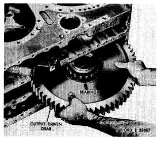
Figure 188. Removing output driven gear
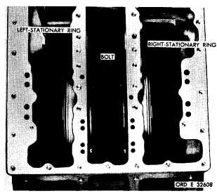
r e t a i n t h e r i g h t - a n d l e f t - b r a k e a p p l y c am
stationary rings (fig. 189).
a t . Remove left-brake apply cam station-
ary ring (fig. 190). Do not remove ring seal
and expander from ring unless replacement is
n e c e s s a r y.
a u . Remove right-brake apply cam sta-
t i o n a r y r i n g ( f i g . 1 9 1 ) . D o n o t r e m o v e r i ng
seal and expander from ring, unless replace-
ment is necessary.
a v . N o f u r t h e r d i s a s s e m b l y o f t h e r e ar
t r a n s m i s s i o n h o u s i n g i s n e c e s s a r y . I f n e c e s-
sary, the various plugs in the housing may be
r e m o v e d t o a i d i n c l e a n i n g t h e h o u s i n g .
1 5 4 . C L E A N I NG
R e f e r t o p a r . 7 1 f o r c l e a n i n g r e c o m m e n-
dations.
1 5 5 . I N S P E C T I O N A N D R E P A IR
R e f e r t o p a r . 7 2 f o r g e n e r a l i n s p e c t i on
and repair recommendations. Repair and re-
b u i l d p o i n t s o f m e a s u r e m e n t f o r f i t s , c l e a r-
ances and wear limits are indicated by small,
lower case letters in figs. 377, 378, 379 and
380, fold-outs 6, 7, 8 and 9. Refer to pars.
240 through 243 for wear limits information.
1 3 4
Figure 189. Top view of transmission rear housing,
showing bolts which retain brake apply cam
stationary rings
1 5 6 . A S S E M B L Y ( f i g s . 3 7 7 , 3 7 8 , 3 7 9 a nd
380, fold-outs 6, 7, 8 and 9)
a. Install any plugs in transmission rear
h o u s i n g 2 5 t h a t w e r e r e m o v e d f o r c l e a n i n g
p u r p o s e s.
b . If ring seal and expander were re-
moved from right-brake apply cam stationary
ring, install new replacements (fig. 191).
c . Install rightbrake apply cam station-
a r y r i n g i n t h e t r a n s m i s s i o n r e a r h o u s i n g
(fig. 191).
d . I f r i n g s e a l a n d e x p a n d e r w e r e r e-
m o v e d f r o m l e f t - b r a k e a p p l y c a m s t a t i o n a ry
ring, install new replacements (fig. 190).
e . Install the left-brake apply cam sta-
tionary ring in the transmission rear housing
(fig. 190).
f . I n s t a l l f o u r 3 / 8 - 2 4 s e l f - l o c k i n g , b o l ts
with flat washers (fig. 189). Torque the bolts
to 41-49 pound-feet.
g . I f b e a r i n g s w e r e r e m o v e d f r o m o u t-
put driven gear 49 (fig. 379, fold-out 8) in-
stall an inner bearing race assembly on each
side of the gear (fig. 188). Press the bearing
until firmly seated on the gear.
|
|


