PAR 1 5 6
REAR HOUSING REBUILD
C H A P 5, SEC X V I II
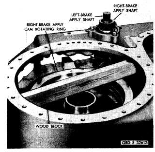
Figure 194. Wood block installed to temporarily retain
cam rotating ring
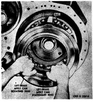
Figure 195. Installing left-brake apply cam rotating ring
sary to prevent damaging the right- and left-
brake apply shafts (fig. 194).
ad.
Install
12
steel
balls
in
the
left-
b r a k e a p p l y c a m s t a t i o n a r y r i n g . I n s t a l l r o -
tating ring (fig. 195).
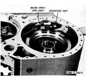
Figure 196. Installing left-brake adjusting nut
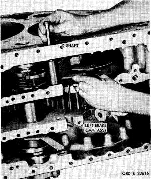
Figure 197. Installing left-follower link shaft
a e . Assemble items 3 through 14 (fig.
3 7 9 , f o l d - o u t 8 ) a n d i n s t a l l a s i n f i g . 1 9 6.
Install brake adjusting nut on the brake link,
approximately 1/2 inch (fig. 196).
a f . While holding the left-brake cam as-
s e m b l y a g a i n s t s p r i n g p r e s s u r e , i n s t a l l t he
follower link shaft (fig. 197).
1 3 7
|
|