*C2
*C2
PAR 1 5 6 - 1 58
LEFT,
RIGHT
STEER
PLANETARIES
REBUILD
C H A P 5, SEC X I X
a m . Install springs and washers and se-
cure with pins (fig. 200). Bend the ends of the
pins to retain them.
a n . I n s t a l l r e t a i n i n g r i n g s , b r a k e a ir
v a l v e p l a t e s a n d s p r i n g s o n b r a k e a i r v a l ve
bracket as shown (fig. 201).
a o . Install right- and left-air valve plate
assemblies with bracket and secure with two
3/8-16
self-locking
bolts.
Torque
bolts
to
36-43 pound-feet.
Section
1 5 7 . D E S C R I P T I O N
a p . Install the brake coolant pump idler
gear shaft and secure with one 3/8-16 x 3-1/4
b o l t ( f i g . 1 7 6 ) . T o r q u e t h e b o l t t o 2 6 - 3 2
p o u n d - f e e t.
a q . Install the bearing in the brake pump
idler gear and secure with the snap ring (fig.
176).
a r. Install the idler gear with the bearing
onto the shaft and secure it with the snap ring
(fig. 176).
X I X . L E F T - A N D R I G H T - S T E E R P L A N E T A R I E S — R E B U I LD
e . R e m o v e t h e r e t a i n i n g r i n g f r o m t he
r i n g g e a r a s s e m b l y ( f i g . 2 0 3 ).
Refer to par. 16 for the description of the
left- and right-steer planetaries .
158. DISASSEMBLY (figs, 378 and 380,
fold-outs 7 and 9)
N o t e . All related items not covered
in a through i, below, were removed
from the transmission as outlined in
par. 75, steps 27 through 30 and 40
t h r o u g h 5 4 . N o f u r t h e r d i s a s s e m b ly
of those parts is required. The left-
and right- steer planetary assemblies
are identical; therefore, the follow-
ing disassembly steps apply to both
a s s e m b l i e s.
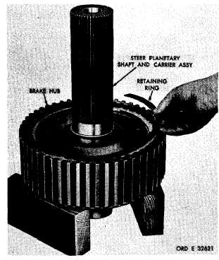
a . Remove the retaining ring that retains
the steer planetary shaft and carrier assembly
in the brake hub (fig. 202).
b . Remove the steer planetary shaft and
c a r r i e r a s s e m b l y ( f i g . 2 0 2 ) .
c . Remove the steer planetary ring gear
from the brake hub (fig. 203).
d . R e m o v e t h e t h r u s t w a s h e r f r o m t he
ring gear assembly (fig. 203).
f . P r e s s o r d r i v e t h e b e a r i n g o u t o f t he
b r a k e h u b ( f i g . 2 0 3 ).
Figure 202. Removing (or installing) steer planetary
carrier and shaft retaining ring
1
3
9
|
|