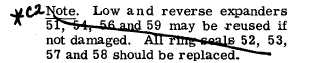
*C2
*C2
PAR 181-183
L O W , R E V E R S E P I S T O N S A N D H O U S I N G R E B U I LD
C H A P 5, SEC X X I V
i. Install spindle replacer 8351266 on the
planetary carrier and position the spindle for
installation (fig. 217).
N o t e . Be sure that the slot on the
spindle is indexed properly with its
lock pin bore in the carrier (fig. 217).
j . U s i n g a p r e s s a n d s p i n d l e r e p l a c er
8351266, install the planetary carrier spindle
( f i g . 2 1 7 ) . T h e s p i n d l e r e p l a c e r w i l l b o t t om
against the carrier when the spindle is proper-
ly positioned in the carrier.
k . Install the lock pin, using a hammer
and punch (fig. 213). Drive the lock pin flush
to 0.030-inch below the carrier surface.
l . Install the remaining five spindles 7
(fig. 377, fold-out 6) and pinions 14, with rol-
lers 10 and 12, thrust washers 8 and 15, lock
pins 16 and spacers 9, 11 and 13 in the same
manner as described in b through k , above.
—
m . Install bearing 20 in reverse-range
carrier support 18. Install retaining ring 21.
n . I n s t a l l r e v e r s e - r a n g e p l a n e t a r y c a r-
r i e r a s s e m b l y 6 i n t h e c a r r i e r s u p p o r t 1 8.
Press on the carrier assembly until it bottoms
in the support.
S e c t i o n X X I V . L O W - A N D R E V E R S E - R A N G E P I S T O N S A N D H O U S I N G — R E B U I LD
1 8 2 . D E S C R I P T I O N
The low- and reverse-range clutch pistons
a r e c o n t a i n e d i n a c o m m o n , m a c h i n e d s t e el
h o u s i n g . T h e p i s t o n s , p i s t o n r e t u r n s p r i n g s,
retainers, ring seals, seal ring expanders and
r e t a i n e r r i n g s c o n t a i n e d i n t h i s h o u s i n g f or
low- and reverse-range are identical and inter-
c h a n g e a b l e .
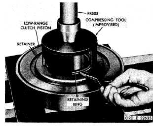
1 8 3 . D I S A S S E M B L Y ( f i g . 3 7 6 , f o l d - o u t 5)
a . P o s i t i o n t h e l o w - a n d r e v e r s e - r a n ge
c l u t c h p i s t o n h o u s i n g a s s e m b l y i n a p r e s s
(fig. 218).
b . U s i n g a c o m p r e s s i n g t o o l ( f i g . 3 8 ) ,
remove the retaining ring retaining the piston
r e t u r n s p r i n g r e t a i n e r ( f i g . 2 1 8 ) . R e m o ve
the retainer.
c . Install eighteen piston return springs
49 (fig. 376, fold-out 5).
d . R e m o v e t h e l o w - r a n g e c l u t c h p i s t on
( f i g .
2 1 8 ) .
e . Remove ring seal 52 and expander 51
( f i g . 3 7 6 , f o l d - o u t 5 ) f r o m l o w - r a n g e c l u t ch
piston 50.
f . Remove ring seal 53 and expander 54
from piston housing 55 .
g . R e m o v e r e v e r s e - r a n g e c l u t c h p i s t on
60, piston return springs 61, retainer 62, re-
taining ring 63, ring seals 57 and 58, and ex-
panders 56 and 59 in the same manner as de-
scribed for low-range in b through f , a b o v e.
—
Figure 218. Removing (or installing) retaining ring
for low-range piston return spring retainer
1
4
9
|
|