PAR 206-211
T U R B I N E S H A F T R E B U I L D
C H A P 5, SEC X X I X
d. Install the output coupling with the
bear~ng into the transmission housing. Install
the retaining ring (fig. 232).
– $c~ e. Po~i~ion the transmission housing on
its b~ttom side. Install the accumulator bcdy
and gasket. Secure the body with four 3/8- 16
x 1-l/2 and two 3/8-16x 2-1/2-inch cap screws
with lock washers (fig. 233).
+@ $ Install the oil filler tube assembly and
gasket. Secure the assembly with four 3/8- 16
x 1 cap screws with lock washers. Install the
gage rod cap.
~. Install the diaphragm assemb”ly in its
housing bore (fig. 233).
#C~h. Install the,iiaphragmclamp plate over
the h=b of the diap:magm assembly (fig. 232).
Aline the bolt holes in the plate with the dia-
phragm :Lssembly. Install four 3/8-24x 2- l/2-
inch self -locking d iaphra.gm bolts (fig. 233).
i. 1 ns t a 11 two preformed packings on
transmission housing (fig. 232 ).
~ Install two hook-type seal rings on hub
of diaphragm assembly (fig. 232).
Section XXIX. TURBINE SHAFT — REBUILIJ
207. DESCRIPTION
The turbine shaft, of machined s t e e 1,
serves as the torque converter output shaft.
It is the input drive member to the transmis-
.—. ,
sion range gearing, and is splined to the high-
range clutch hub, intermediate-range and low-
range sun gears. The shaft is splined to the
turbine of the torque converter assembly.
208. DISASSEMBLY (fig. 375, fold-out 4)
a. Remove four seal rings 1 and 3 from
turb~e shaft 2.
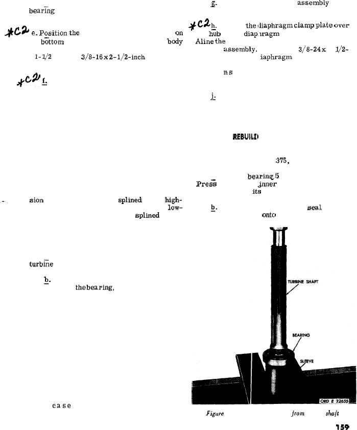
~. Using a sleeve which will contact the
inner race of thebearing, support the assem-
bly in a press. Press the shaft out of the
bearing (fig. 236).
209. CLEANING
Refer to par. 71 for cleaning recommen-
dations.
210. INSPECTION AND REPAIR
-.
Refer to par. 72 for general inspection
and repair recommendations. Repair and re-
build points of measurement for fits, clear-
ances and wear limits are indicated by small,
lower case letters in fig. 375, fold-out 4.
Refer to par. 238 for wear limits information.
211. ASSEMBLY (fig.
a. Install bearing
:375, fold-out 4)
5 onto turbine shaft 2.
Pres= the bearing im& race until it is firmly
seated against it; shoulder on the shaft. -
~. Install three hook-type seal rings 3
and one seal ring 1 ontcl turbine shaft 2.
ml,!
Figure 236. Removing bearing jrom turbine shu/t
159
|
|