P A R 2 2 7 , S T E P S 2 3 - 2 6
A S S E M B LY
C H A P 5, SEC X X X I II
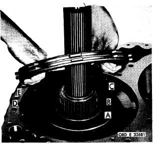
Figure 262 (Step 23)
Install thrust washer (A) and sleeve (B) onto
l o w - r a n g e c a r r i e r a n d s h a f t a s s e m b l y ( C ) .
A l t e r n a t e l y i n s t a l l t h r e e e x t e r n a l - ( D ) a nd
three
internal-splined
(E),
reverse-range
c l u t c h p l a t e s , b e g i n n i n g w i t h a n e x t e r n a l -
splined plate (D).
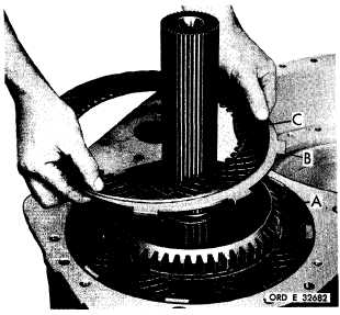
Figure 263 (Step 24)
Install reverse-range ring gear assembly (A),
chamfered side up. Install an external-splined
( B ) a n d t h e r e m a i n i n g i n t e r n a l - s p l i n e d ( C ),
r e v e r s e - r a n g e c l u t c h p l a t e . A l i n e t h e t a n gs
of plates (B) and center the plates carefully.
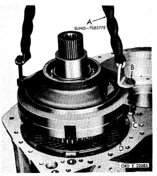
Figure 264 (Step 25)
Using sling (A) and two 7/16-14 bolts (B) and
n u t s ( C ) , i n s t a l l r e v e r s e - r a n g e c a r r i e r a n d
support housing assembly (D).
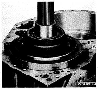
Figure 265 (Step 26)
I n s t a l l t w o 3 / 8 - 1 6 s c r e w s ( A ) t h a t r e t a in
r e v e r s e - r a n g e c a r r i e r s u p p o r t h o u s i n g ( B ).
T i g h t e n s c r e w s e v e n l y u n t i l h o u s i n g ( B ) is
f i r m l y s e a t e d.
1 6 9
|
|