P A R 2 2 7 , S T E P S 6 3 - 6 6
A S S E M B LY
C H A P 5, SEC X X X I II
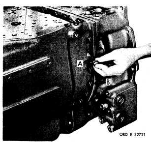
Figure 302 (Step 63)
I n s t a l l t h i r t y - t h r e e 7 / 1 6 - 1 4 x 1 - 1 / 2 b o l t s
( A ) a n d l o c k w a s h e r s ( B ) . U s i n g a 5 / 8 - i n ch
wrench, torque bolts to 42-50 pound-feet.
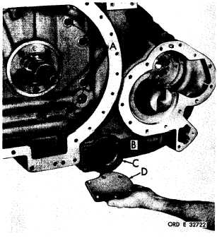
Figure 303 (Step 64)
Using a 5/8-inch wrench, tighten five 7/16-14
x 4 self-locking bolts (A) to 54-65 pound-feet
torque. Install oil screen (B), gasket (C) and
cover (D).
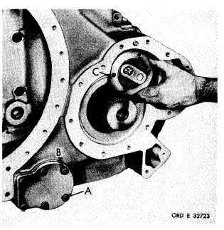
Figure 304 (Step 65)
I n s t a l l s i x 3 / 8 - 1 6 x 1 - 1 / 8 b o l t s ( A ) a n d l o ck
w a s h e r s ( B ) . U s i n g a 9 / 1 6 - i n c h w r e n c h,
torque bolts to 26-32 pound-feet. Install out-
put oil pump assembly (C).
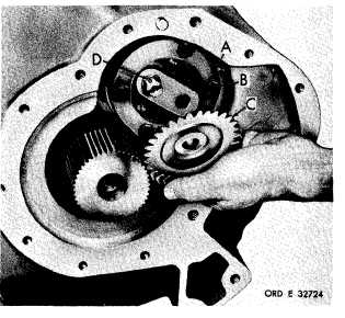
Figure 305 (Step 66)
Secure output oil pump assembly (A) with four
3/8-16
x
2
self-locking
bolts
(B).
Using
a
9 / 1 6 - i n c h w r e n c h , t o r q u e t h e b o l t s t o 3 6 - 43
p o u n d - f e e t . I n s t a l l o i l p u m p d r i v e n g e a r ( C)
and key (D).
1 7 9
|
|