ASSEMBLY
CHAP 5, SEC XX XIII
P A R 2 2 7 , STEPS 7 1 - 7 4
Figure 310 (Step 71)
Using wrench (A), apply the left brake. Using
a 1-inch wrench, tighten left-output coupling
bolt (B) to 337-385 pound-feet torque. Install
lock ring (C) and coupling nut (D) temporarily.
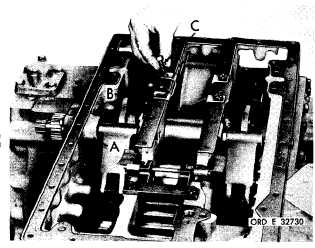
Figure 311 (Step 72)
I n s t a l l g a s k e t ( A ) . I n s t a l l o i l b a f f l e ( B ) a nd
secure with four 3/8-16 x 1 bolts (C). Using
a 9 / 1 6 - i n c h w r e n c h , t o r q u e b o l t s t o 3 6 - 43
p o u n d - f e e t .
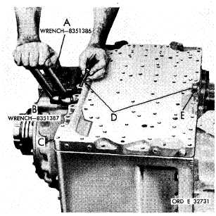
Figure 312 (Step 73)
Using wrenches (A) and (B), apply the trans-
mission right and left brakes slightly. Install
transmission rear housing cover (C) and two
3/8-16 x 2-1/4 bolts (D) with lock washers (E),
at opposite sides.
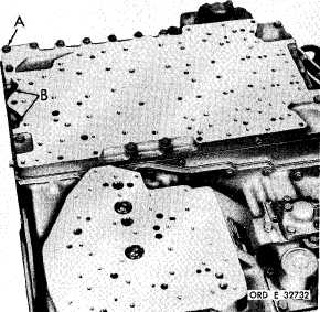
Figure 313 (Step 74)
I n s t a l l e i g h t e e n 3 / 8 - 1 6 x 2 - 1 / 4 ( A ) a n d t wo
3 / 8 - 1 6 x 1 - 3 / 8 b o l t s ( B ) w i t h l o c k w a s h e r s .
U s i n g a 9 / 1 6 - i n c h w r e n c h , t o r q u e b o l t s t o
2 6 - 3 2 p o u n d - f e e t.
1 8 1
|
|