TM 9-2520-272-34&P
4-19.
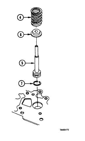
DISASSEMBLE RIGHT END COVER ASSEMBLY
(SHEET 5 OF 16)
4 Remove large spring (4).
5 Remove brake coolant valve stem (5) with coolant
valve (6) and seal ring (7) attached.
6 Remove coolant valve (6) from valve stem (5).
7 Remove seal ring (7) from stem (5).
FOLLOW-ON PROCEDURE: Install brake coolant
valve components.
Refer to paragraph 4-21.
End of Task 3
TASK 4. REMOVE BRAKE APPLY INDICATORS AND
LEFT BRAKE APPLY SHAFT
COMMON TOOLS:
Pliers, retaining ring, internal
Screwdriver, flat tip
SUPPLIES:
Petrolatum (Item 149 Appendix C).
Rig, wiping (Item 15, Appendix C)
Tape, masking (Item 20, Appendix C)
Wooden Blocks, 2 x 4 x 18 inches (2 required) (Item 2 Appendix C)
PRELIMINARY PROCEDURE:
• No preliminary procedure is required for removal of indicators at this level of
maintenance.
• Right end cover removal provides access to left brake apply shaft. Refer to paragraph
4-7.
NOTE
Right end cover is turned outside up.
Outer retainin9 ring may or may not be on left brake apply shaft and right
brake apply cam shaft.
brake linkage.
Left brake apply shaft must be held in place by a wood block or by hand to
keep it from falling out of the end cover after removal of retaining rings and
indicators
Go to Sheet 6
4-100
Para. 4-19, Task 4
These retaining rings are supplied to retain external
|
|