TM 9-2520-272-34&P
4-21.
ASSEMBLE RIGHT END COVER ASSEMBLY
(SHEET 18 OF 22)
TASK 6. INSTALL BRAKE APPLY REGULATOR VALVE COMPONENTS
COMMON TOOLS:
Extension, socket wrench, 1/2 inch square drive, 6 inch
Gage, thickness (containing one blade 0.025 inch thick)
Handle, socket wrench 1/2 inch square drive
Socket, socket wrench, 1/2 inch square drive, 1/2 inch
Wrench torque, 0-175 ft-lb
SUPPLIES:
Lubricating Oil (Item 10, Appendix C)
Rag, wiping (Item 15, Appendix C)
1
2
3
4
5
6
7
8
9
PRELIMINARY PROCEDURE: Right brake support
assembly is installed. Refer to procedure TASK 4.
NOTE
Right end cover assembly is turned inside up.
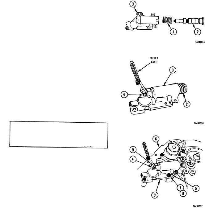
Install spring (1) on brake apply regulator valve
assembly (2).
NOTE
Valve must move freely in body by its own
weight.
Apply lubricating oil to valve assembly (2).
Install spring (1) and regulator valve assembly (2) in
brake apply body assembly (3).
WARNING
Spring-loaded parts can fly and injure you.
Always follow specified instructions when
installing covers to valve assemblies.
Push valve assembly (2) through body (3) so that nut (4)
on end of valve assembly extends out of body.
Install 0.025 inch feeler gage behind nut (4) to retain
valve (2) and spring (1) in body (3).
Install body (3) on two dowel pins (5) located on right
end cover assembly (6) housing.
Using socket, install five bolts (7) and washers (8) in
body assembly (3).
Using torque wrench tighten bolts (7) to 17-20 lb-ft
(23-27 N·m).
Remove feeler gage from nut (4).
FOLLOW-ON PROCEDURE: Install left brake appIy shaft. Refer to this paragraph, TASK 7.
End of Task 6
Go to Sheet 19
Para. 4-21, Task 6
4-143
|
|


