TM 9-2520-272-34&P
4-26.
DISASSEMBLE BEVEL GEAR ASSEMBLY
1
2
3
4
5
6
7
8
9
10
11
12
13
14
I
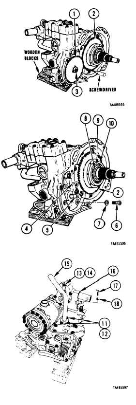
Position bevel gear assembly on wooden blocks as
shown.
Wedge screwdriver between input oil pump driven gear
(1) and input oil pump drive gear (2) to prevent gears
From turning.
Using 3/4 inch socket, remove nut (3) that retains gear
(1).
Using pry bar, remove gear (1).
Using diagonal cutting pliers, remove woodruff key (4)
from input oil pump shaft (5).
)
Using 1/2 inch socket and extension, remove seven
bolts (6 and washers (7).
Using external retaining ring pliers, remove retaining
(
ring 8).
Remove spacer (9).
Using two pry bars, remove gear (2) and bearing (10).
Using arbor press, remove bearing (10) from gear (2).
Position bevel gear assembly on wooden blocks as
shown.
Using 1/2 inch socket and extension, remove two bolts
(11) and washers(12) and one bolt(13) and washer (14)
that retain scavenge tube assembly (15). Remove tube
assembly (15).
NOTE
If output pump assembly (16) is to be sent to
depot for overhaul, do Step 13. If not, go to
Step 14.
Using 1/2 inch socket, reinstall washer (14) and bolt
(13). Using torque wrench torque bolt (13) to 17-20
lb-ft (23-27 N•m).
Using 9/16 inch universal socket, extension and
adapter, remove two bolts (17) and washers (18) that
retain output pump assembly (16). Remove pump
assembly (16).
Go to Sheet 3
4-164
Para. 4-26, Task 1
(SHEET 2 OF 4 )
|
|


