4-28.
DISASSEMBLE CENTER HOUSING
(SHEET 8 OF 19)
TASK 3. REMOVE STEER CONTROL ASSEMBLY
COMMON TOOLS:
Extension, socket wrench, 3/8 inch square drive, 6 inch
Handle, socket wrench, 3/8 inch square drive
Socket, socket wrench, 3/8 inch square drive, 1/2 inch
Socket Head Screw Attachment, socket wrench,
3/8 inch square drive, 3/8 inch hex plug end
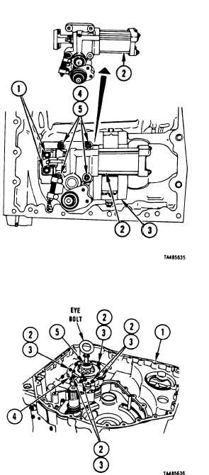
1 Using 3/8 inch socket head screw attachment, remove
two socket head screws (1) holding steer control
assembly (2) to hydrostat (3).
2 Using 1/2 inch socket, remove four bolts (4) and
washers (5) holding steer control assembly (2) to
hydrostat (3).
3 Remove steer control assembly (2) from hydrostat
FOLLOW-ON PROCEDURE: Install steer control
assembly. Refer to paragraph 4-30.
End of Task 3
(3).
TASK 4. REMOVE HYDROSTATIC PUMP AND MOTOR
ASSEMBLY (HYDROSTAT)
COMMON TOOLS:
Extension, socket wrench, 3/8 inch square drive, 12 inch
Handle, socket wrench, 3/8 inch square drive
Hoist, 100 pound minimum capacity
Pliers, retaining ring, external
Socket, socket wrench, 3/8 inch square drive, 9/16 inch
SPECIAL TOOLS:
S-hook (19207) 11650102
TM 9-2520-272-34&P
1
2
3
Go
Using rotary control handle on maintenance stand, rotate transmission (1) to right end up.
Using socket, remove six bolts (2) and washers (3) holding hydrostat (4) to transmission (1).
Install 7/8-9 eyebolt in threaded hole (5) located in center of shaft on hydrostat (4).
to Sheet 9
Para. 4-28, Task 3
4-179
S U P P L I E S
Eyebolt, 7/8-9
|
|