
| Tweet |

Custom Search
|
|

|
||
 TM 9-2815-220-24
FUEL INJECTION PUMP ASSEMBLY REPLACEMENT
0115 00
INSTALLATION (Continued)
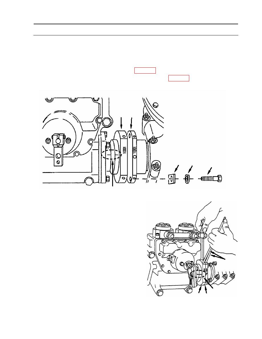
12. Position fuel injection pump coupling sleeves (16 and 17) as shown, making sure timing
marks (A) remain in alignment. Drive sleeve (17) may be pushed back to disengage from
spline, rotated, then pulled forward to re-engage.
13. Apply a small amount of Lubriplate (item 23, WP 0173) to the threads of four screws (19).
14. Install four screws (19) with new lock washers (20) (item 90, WP 0175), spacers (21) to
couple sleeves (16, 17).
16
17
21
20
19
A
15. Remove backlash from drive shaft coupling (17).
a. Position two 5/16 drift punches (37) in
sleeves (16, 17) alignment holes. Hold
coupling sleeve (16) stationary with
timing marks (A) aligned, then rotate
coupling sleeve (17) counterclockwise, as
37
viewed from damper end of engine, to
remove backlash from pump drive shaft.
A
16 17
WP 0115 00-13
|
||
|
||


