
| Tweet |

Custom Search
|
|

|
||
 TM 9-2815-220-24
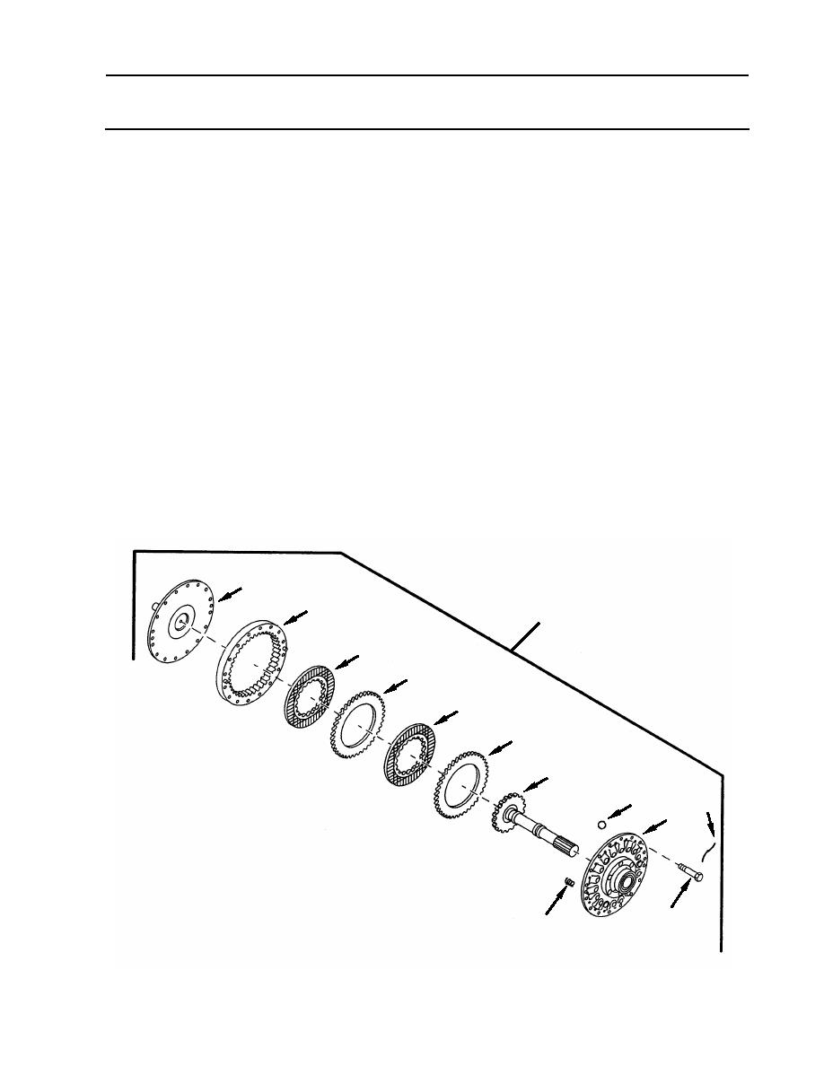
FAN DRIVE CLUTCH ASSEMBLY AND ASSOCIATED PARTS
REPLACE/REPAIR
0129 00
DISASSEMBLY (Continued)
3. Separate flange (31) from hub (32).
a. Place clutch assembly (26) in machinist's vice with hub (32) up.
b. Cut, remove, and discard locking wire (33) from 16 screws (34).
c. Remove 14 of the 16 screws (34) securing fan drive hub assembly (32) to flange (31).
Leave two oppositely positioned screws (34) in place.
d. Alternately loosen the remaining two screws (34) until flange (31) and housing
assembly (35) comes off hub (32) as a unit.
NOTE
Early model clutch assemblies used 15 ball bearings. On assembly,
use only six of the ball bearings. Doing so will increase gear train life.
4. Remove three springs (36) and six ball bearings (37) from fan drive hub assembly (32).
Discard springs and ball bearings.
5. Remove four clutch disks (38, 39).
6. Remove shaft assembly (40) from fan drive hub assembly (32).
7. Separate housing assembly (35) from flange (31).
31
35
26
39
38
39
38
40
37
33
32
34
36
WP 0129 00-7
|
||
|
||


