
| Tweet |

Custom Search
|
|

|
||
 TM 9-2815-220-24
CRANKSHAFT REPLACE/REPAIR
0139 00
REMOVAL (Continued)
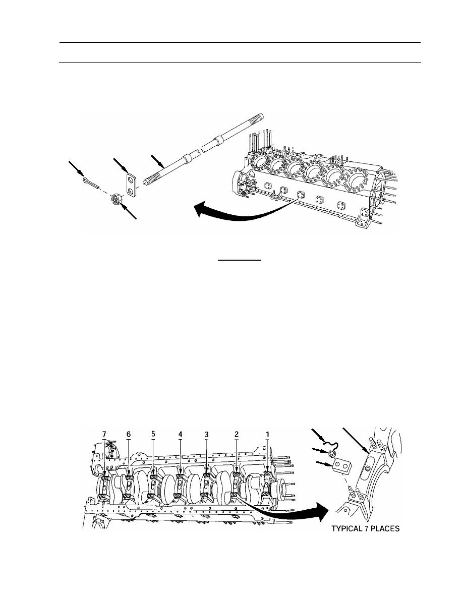
2. Separate cotter pins (3), slotted nuts (4), and washer-plates (5) from tie-rods (1). Discard
cotter pins (3).
1
5
3
4
CAUTION
The main bearing caps are marked 1 through 7 (front to rear) to
identify their locations. Identifying numbers also appear on bearing
web inside crankcase. The caps are not interchangeable with each
other and must be returned to their original positions during
installation. Failure to comply may result in premature engine
failure.
NOTE
The removal procedure for any one main bearing cap is identical to
any other main bearing cap, only one is described.
3. Remove main bearing caps (6).
a. Remove lock wire (7) and four slotted nuts (8). Discard lock wire.
b. Remove two washer-plates (9).
6
7
8
9
WP 0139 00-3
|
||
|
||


