
| Tweet |

Custom Search
|
|

|
||
 TM 9-2815-220-24
CAMSHAFT, DRIVE GEARS, AND ASSOCIATED PARTS REPLACEMENT
0146 00
INSPECTION (Continued)
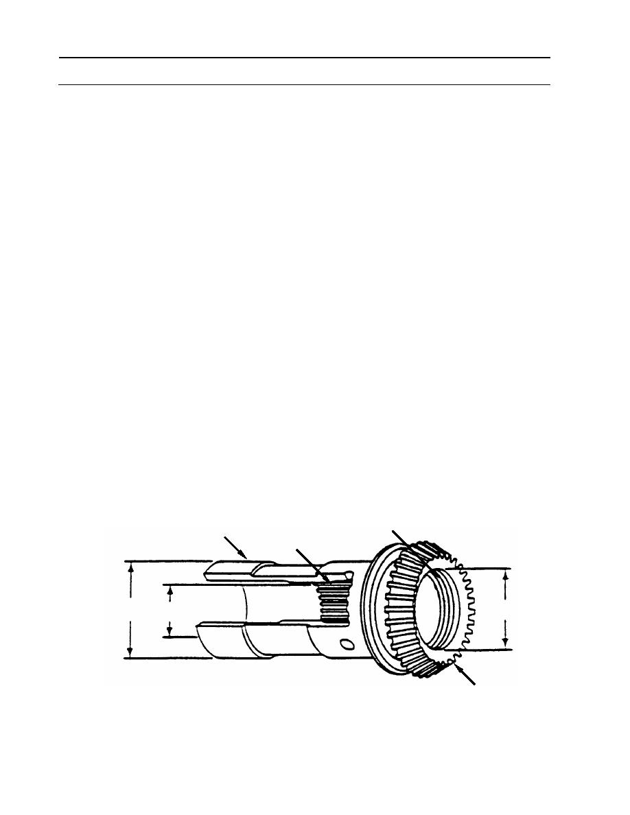
4. Inspect bevel gear shaft (7).
a. Visually inspect gear shaft (7).
(1) Check internal spline (A) and external gear teeth (B). Look for obvious damage
(severe wear, broken teeth, or heat damage). If any is found discard bevel gear
shaft (7).
(2) Inspect snap ring groove (C) to assure that snap ring will remain in place. If snap ring
groove (C) is washed out at edges, discard gear shaft (7).
b. Measure internal spline (A) diameter (D) between two 0.0600-inch (1.524-mm) diameter
pins.
(1) Reject gear shaft if dimension is greater than 1.1055 inches (28.0797 mm).
c. Measure and record outside diameter (E) of gear shaft (7).
(1) Reject gear shaft if dimension is less than 1.6215 inches (41.1861 mm).
(2) Measurement will also be used for fit of gear shaft (7) to adapter (22) in step 6c.
d. Measure and record inside diameter (F) of gear shaft (7).
(1) Reject gear shaft if dimension is greater than 1.2725 inches (32.3215 mm).
e. Calculate fit of lube fitting (9) to bevel gear shaft (7).
(1) Subtract measurement (A) taken in step 1 from measurement (F) of step 4d.
(2) Reject both pieces if fit is looser than 0.0020 inch (0.0508 mm).
C
7
A
E
F
D
B
WP 0146 00-6
|
||
|
||


