
| Tweet |

Custom Search
|
|

|
||
 TM 9-2815-220-24
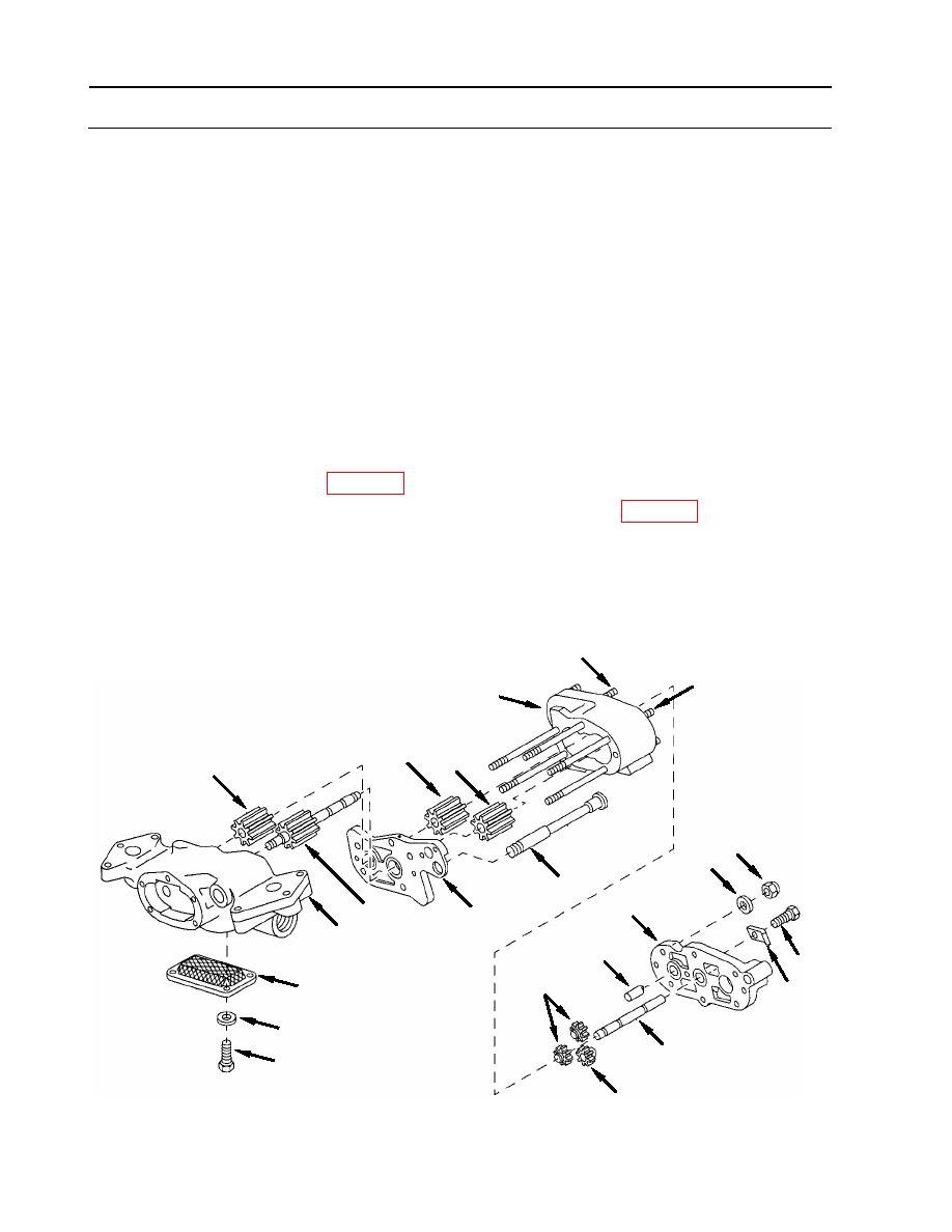
OIL PUMP REPAIR
0154 00
ASSEMBLY
1. Install screen (45).
a. Secure to pressure housing (28) using four screws (46) with flat washers (47).
2. Install gear shaft (43) and impeller (44) into housing assembly (28).
3. Install spacer (42) onto pressure housing (28).
4. Install impeller driven shaft (41) into scavenge housing (25).
5. Install impeller (24) onto gear shaft (43) after spacer (42).
6. Install impeller (23) onto impeller driven shaft (41) after spacer (42).
7. Install scavenge housing (25) onto pressure housing (28).
8. Install shaft (40) reserve compartment impellers (38 [two]) and (39 [one]) into scavenge
housing assembly (25).
9. Install scavenge compartment cover (33).
a. Apply lubricant (item 23, WP 0173) to threads of six studs (54, 55).
b. Secure cover (33) using six new self-locking nuts (36) (item 33, WP 0175), with flat
washers (37).
c. Torque self-locking nuts (36) to 125-150 inch-pounds (14-17 Nm).
10. Install lock plate (35).
a. Secure with screw (34).
54
55
25
23
24
44
36
37
18
33
43
42
28
40
34
38
45
35
47
41
46
39
WP 0154 00-14
|
||
|
||


