
| Tweet |

Custom Search
|
|

|
||
 TM 9-2815-220-24
FUEL INJECTION ADVANCE CONTROL REPAIR
0161 00
INSPECTION (Continued)
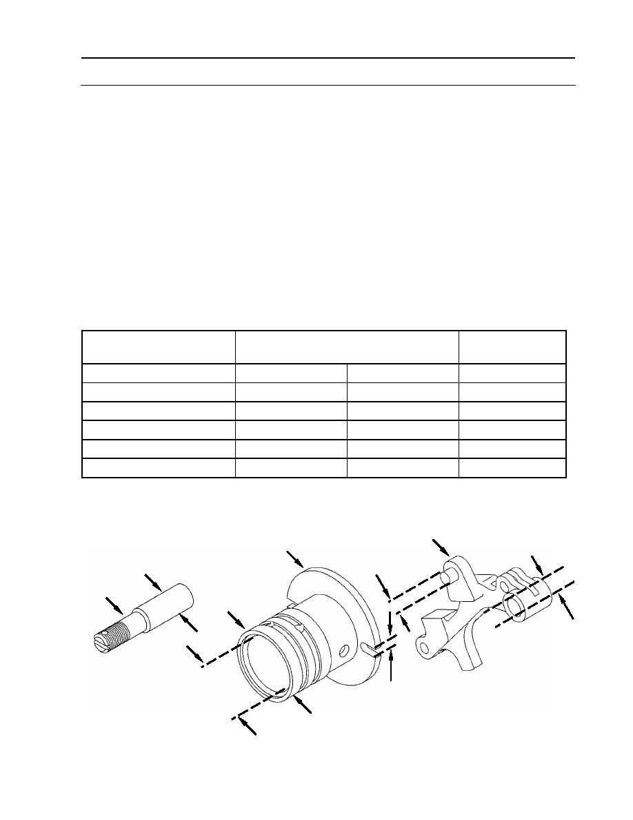
4. Measure outside diameter (A) of both threaded pins (11). Replace threaded pins if not within
specifications in the following table.
5. Measure inside diameter (B) of hole in two flyweights (16). Replace flyweights if not within
specifications in the following table.
6. Measure outside diameter (C) of pin on two flyweights (16). Replace flyweight assemblies if
not within specifications in the following table.
7. Measure outside diameter (D) of fluid regulating valve (14). Replace fluid regulating valve if
not within specifications in the following table.
8. Measure inside diameter (E) of fluid regulating valve (14). Replace fluid regulating valve if
not within specifications in the following table.
9. Measure width of slots (F) in fluid regulating valve (14). Replace fluid regulating valve if not
within specifications in the following table.
Location
Sizes and Fit of New Parts
Wear Limits
inches (mm)
A (Threaded pins)
0.3110 (7.8994)
0.3115 (7.9121)
None
B (Flyweight holes)
0.3120 (7.9248)
0.3130 (7.9502)
None
C (Flyweight pins)
0.2500 (6.3500)
0.2510 (6.3754)
0.2490 (6.3246)
D (Regulating valve)
1.8710 (47.5234)
1.8715 (47.5361)
1.8708 (47.5183)
E (Regulating valve)
1.5015 (38.1381)
1.5020 (38.1508)
1.5030 (38.1762)
F (Regulating valve slots)
0.2510 (6.3754)
0.2550 (6.4770)
0.2560 (6.5024)
16
14
A
C
11
D
B
E
F
WP 0161 00-9
|
||
|
||


