
| Tweet |

Custom Search
|
|

|
||
 TM 9-2815-226-34-1
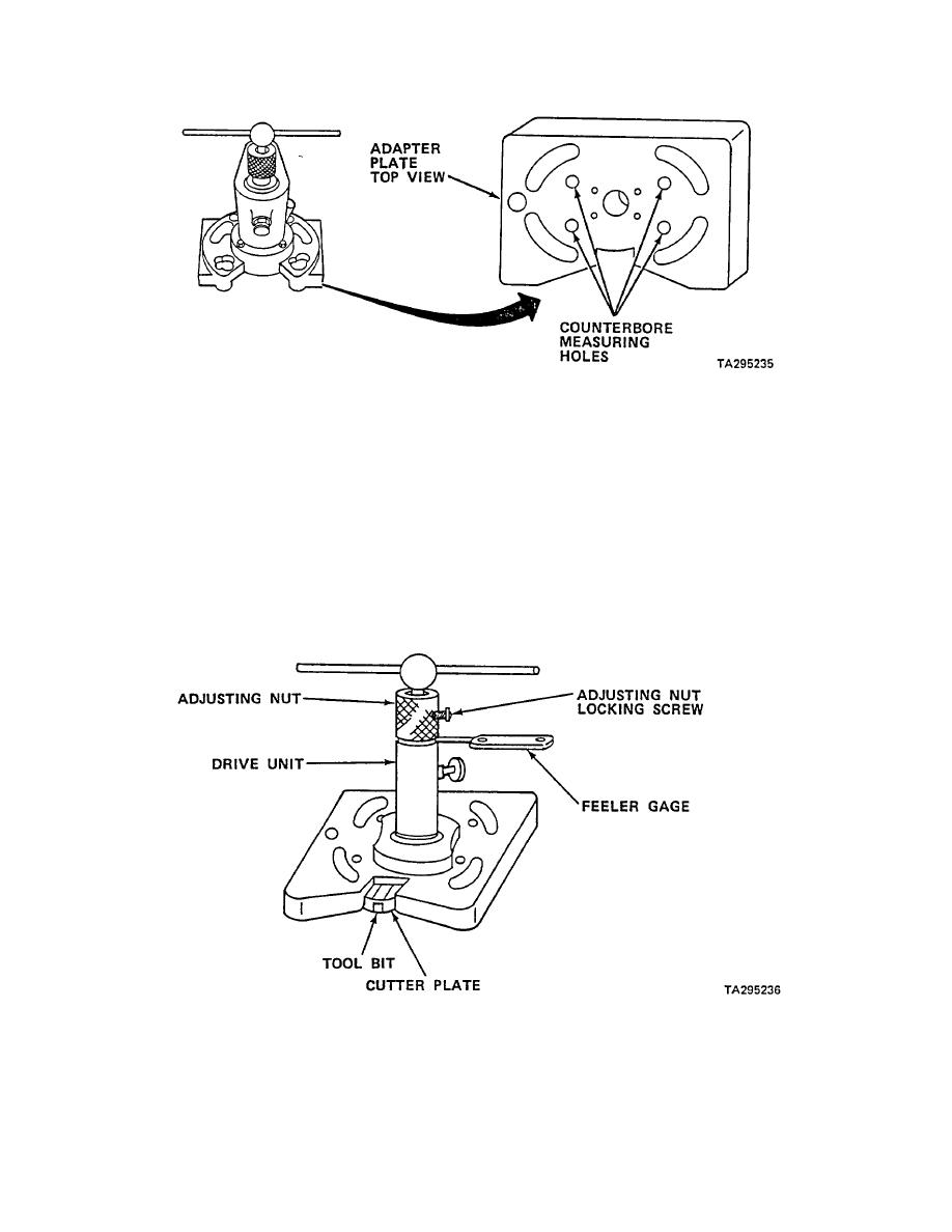
NOTE:
DRIVE UNIT NOT SHOWN INSTALLED ON TOP VIEW OF PLATE FOR CLARITY
(p) Place depth gage through counterbore measuring holes in adapter plate.
(q) Take four depth readings. Average of four readings will represent present depth of counterbore.
(r) Loosen adjusting nut locking screw.
(s) Rotate adjusting nut in counterclockwise direction until tool bit is resting on counterbore ledge.
(t) To set depth of cut, continue rotating adjusting nut until feeler gage of required thickness can be
inserted between nut and top of drive unit. For example, if 0.005 in. (0.127 mm) of material is to be
removed from counterbore ledge, use 0.005 in. (0.127 mm) feeler gage. Ensure that there is no
grease or dirt between adjusting nut and top of drive unit.
3-75
|
||
|
||


