
| Tweet |

Custom Search
|
|

|
||
 TM 9-2815-226-34-2
(2) Open test stand bypass valve, suction control valve, and flow control valve.
(3) Back seat all other valves on test stand to prevent leakage.
NOTE
After setting speed control rod assembly to HIGH range, turn crank to left
approximately one turn so that hand load is neutralized.
(4) Set speed control rod assembly at HIGH range.
(5) Check that throttle lever is wide open and secured in that position with spring.
(6) Turn selector valve to ROTAMETER position.
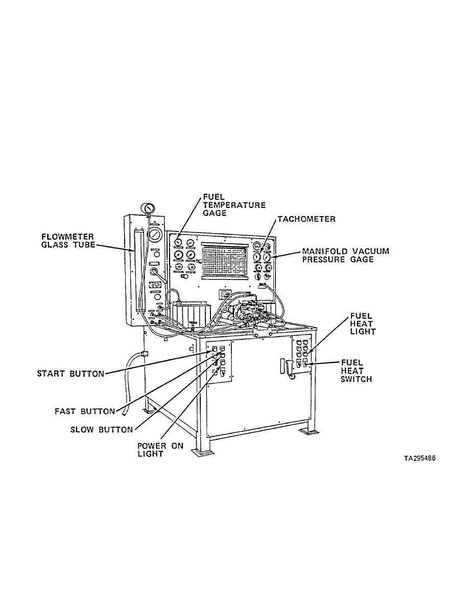
(7) Turn wall mounted power switch to ON position. Check that power ON light comes on.
3-348
|
||
|
||


