TM 9-2815-237-34
2-35.3. (6.2L or 6.5L) FUEL INJECTION PUMPS (DB2829-4523, DB2829-4879, or
DB2831-5149) CALIBRATION USING FUEL INJECTION PUMP TEST STAND
(FTIS) MODEL A8022 (Cont’d)
2-140.16 Change 1
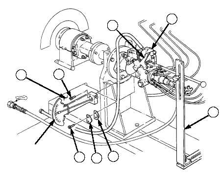
16.
Position throttle arm positioner assembly (3) on bedplate (7) and throttle lever (1).
NOTE
When installing advance indicator, ensure the flat on pointer end
engages into the cam ring slot on fuel injection pump.
17.
Remove two screws (6), timing cover (5), and gasket (4) from fuel injection pump (2) and install
advance indicator with two screws (6).
18.
Remove screw plug from advance indicator block and install quick-connect on advance indicator
block (8).
19.
Attach one end of rubber hose assembly to quick-connect and the other hose assembly end to
auxiliary pressure quick-connect plug on front panel of test stand.
20.
Connect positive red test lead to DC power supply socket marked (+) on test stand, and attach the
alligator clip end of red test lead to the electric shutoff solenoid terminal (9) on fuel injection
pump (2).
21.
Connect black lead to DC black socket marked “P” on test stand and connect alligator clip end of
black lead to ground terminal (10) on fuel injection pump (2).
22.
After installation and hookup of the fuel injection pump has been completed, inspect pump, all
hoses, and related hardware connections before beginning pump calibration. Review operation test
procedures for the FTIS prior to calibrating the fuel injection pump.
2
3
4
5
6
1
7
6
ADVANCE
INDICATOR
|
|